
Method and apparatus for pressure adaptive morphing structure

a morphing structure and adaptive technology, applied in the direction of marine propulsion, vessel parts, vessel construction, etc., can solve the problems of low weight/energy/complexity penalty, weight penalty, and special challenge in the design of morphing wings, so as to achieve the effect of not significantly affecting engine efficiency and stiff structur

Active Publication Date: 2013-02-05
UNIVERSITY OF KANSAS
View PDF16 Cites 28 Cited by
  • Summary
  • Abstract
  • Description
  • Claims
  • Application Information

AI Technical Summary

Benefits of technology

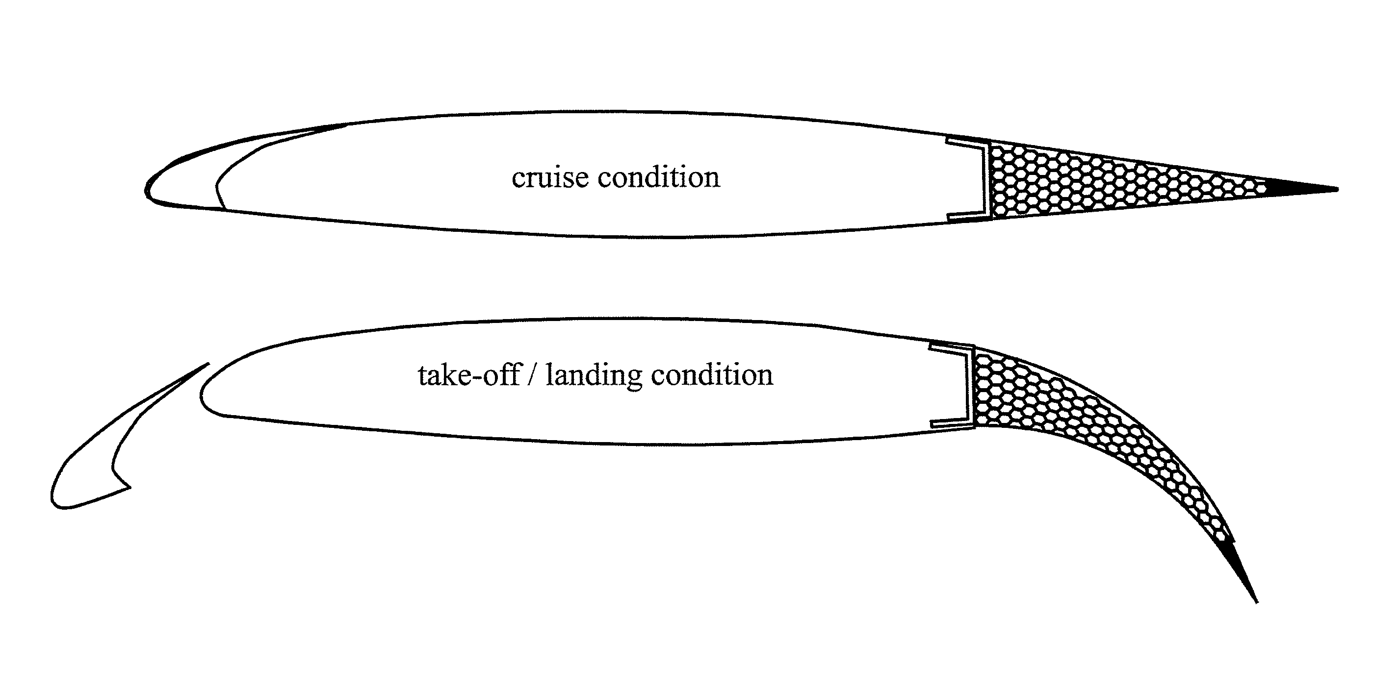
[0059]The invention is a novel adaptive aerostructure is presented that relies on certified aerospace materials and can therefore be applied in conventional passenger aircraft. This structure consists of a honeycomb material which′ cells extend over a significant length perpendicular to the plane of the cells. Each of the cells can contain an inelastic pouch (or bladder) that forms a circular tube when the cell forms a perfect hexagon. By changing the cell differential pressure (CDP) the stiffness of the honeycomb can be altered. Using an external force or the elastic force within the honeycomb material, the honeycomb can be deformed such that the cells deviate from their perfect-hexagonal shape. It can be shown that by increasing the CDP, the structure eventually returns to a perfect hexagon. By doing so, a fully embedded pneumatic actuator is created that can perform work and substitute conventional low-bandwidth flight control actuators. It is shown that two approaches can be taken to regulate the stiffness of this embedded actuator:
[0065]It should be noted that the present invention for an adaptive morphing structure utilizing embedded pressure adaptive honeycomb cells can not only be utilized in various aero-structures including those noted herein and vertical tails, canards stabilizers, but can also be utilized in non aero-structures requiring adaptive morphing or deformation including airfoils in general. For example, the technology could be utilized for blades of a propeller, rotor or turbine, or for a sail. A specific example could be an adaptive blade for a wind power generator where the blades of the generator are adapted to morph or deform based on the current direction of the wind in order to maximize efficiency. Another specific example is that the blades of a turbine or compressor can be adapted to morph or deform based on the environmental or load conditions to run more efficiently. The blades for powering a submarine or the various fins for guidance can be morphed for maximum speed, maximum maneuverability, maximum silence, and or stopping abruptly. The adaptive morphing structure could be utilized for fins utilized in various fluid flow or air flow damping or flow control systems.

Problems solved by technology

Matching the performance of bird morphing in combination with a low weight / energy / complexity penalty has proven to be very challenging.
Morphing wing design is especially challenging because its multidisciplinary nature impacts each of the individual groups or categories directly.
For example, a swing wing can be beneficial from an aerodynamic standpoint; however, it also comes with a weight penalty and requires a completely different structural arrangement, which impacts the production and stress engineering groups.
However, few of the morphing technologies have transferred to the civil realm of aviation.
They can exhibit great strains and apply considerable force.
However, they generally exhibit a large power draw due to energy dissipation and their hysteresis can amount to 38%.
Moreover, their bandwidth is generally poor because of thermal saturation issues [5].
Although these designs accomplish large deformations the structure of multiple parts, hinges, and actuators is complex and occupies most of the internal wing volume.
Piezoelectric materials have a lower single-stroke work density than SMAs and generally a limited stroke and force capability.
Although their energy densities are high, their low transfer efficiency requires a relatively large amount of energy to actuate these materials.
In addition, the actuators are relatively slow.
Sweeping the wing backwards to increase the drag divergence Mach number has had an adverse effect on the low-speed lifting capability of the wing.
In addition, LSAs are highly cost sensitive, which makes the addition of a complicated high-lift device less attractive.
This requires extremely stiff and strong components within the extend / retract mechanism, which generally results in a significant weight penalty.
The flap system complicates the wing's trailing edge structure and introduces electrical systems in relatively thin parts of the wing.
Furthermore, the system adds weight to the wing and increases the cost of manufacturing.
The steep slope of the pressure gradient is an indication that the boundary layer will separate at a lower angle of attack than for the thick airfoil, giving rise to an abrupt drop in lift.
Even though the mechanism could work well, the structure lacks an integral torque box that is essential to provide appropriate levels of torsional stiffness.
Even though the flight tests demonstrated advantages of the wing morphing, there were significant drawbacks to the way the morphing was achieved.
This resulted in a relatively heavy and complex actuation system.
Although effective in providing significant wing deformations and smooth transitions, compliant mechanisms are often much more complicated than the control surfaces they are replacing.
At a certain angle of attack, the bubble bursts, no re-attachment occurs, and a sudden drop in lift results.
It was already shown in the 1950s that modification of the nose of a 35° swept wing could result in significant changes in maximum lift coefficient.
In addition, keeping the nose radius tangent to the upper surface contour of the basic airfoil resulted in an increase in leading edge droop.
Because adaptive flaps are integrally attached to the main wing, they do not benefit from the jet effect that exists when a flap is slotted.
In addition, they lack any Fowler motion.
It also induces a significant increase in pitching moment because of high aft loading.
Extracting this energy from the airstream rather than from actuators reduces the size and consequently the weight of the wing-movable.
In addition, the torsional rigidity of the wing was intentionally weakened which must have decreased the flutter and divergence clearance.
The main drawback of twist-active wings is that there is should always be a trade-off between torsional stiffness on the one hand and actuator sizing on the other hand.
Other disadvantages include (a) the added structural weight that is required to bear the torque load that is introduced by sweeping the wing, (b) reduced flap effectiveness, and (c) a spanwise drift over the wing that increases boundary layer thickness and leads to increased drag and reduced aileron effectiveness.
However, this leads to other inconveniences like added structural weight to bear the bending moment of the wing and less volume for fuel storage.
Even though the effectiveness of this wing was excellent, penalties in terms of complexity and the impossibility to store fuel become clear.
In addition, the complex wing structure in combination with the requirement of powerful actuators led to a very high weight penalty.
Wind tunnel tests successfully demonstrated the morphing mechanism, but were inconclusive about the expected drag reduction at transonic and supersonic speeds.
It might be expected that interference-drag penalties occurring in folded position negate the drag reduction due to increased effective sweep and decreased wing area.
Therefore, morphing structures have been limited to the high lift devices such as flaps and slats.
However, due to insurmountable weight problems associated with the swing-wing mechanism Boeing discarded this morphing concept in favor of a fixed delta wing.
The project was cancelled before one prototype was built due to heavy opposition by (among others) environmentalists.
The morphing wing concepts which were conceived for military applications (e.g. F-111, F-14 and F-18 AAW) are therefore unsuitable for commercial applications.
Maintaining such structures can be costly and is, therefore, unattractive for commercial airliners.
Other disadvantages such as the limited ability to store fuel in the wings or a complex control system have prevented morphing technology from transferring from the experimental military aircraft to modern transport aircraft.
As was mentioned before, because adaptive materials have not been certified for use in primary or secondary aircraft structures, applying them on commercial aircraft is still impossible.
Commercial applications of morphing structures can only be viable if certifiable systems (including certifiable materials) are used, direct operating costs are decreased, and structural integrity is maintained.

Method used


Image

  • Method and apparatus for pressure adaptive morphing structure
  • Method and apparatus for pressure adaptive morphing structure
  • Method and apparatus for pressure adaptive morphing structure

Examples


Embodiment Construction

[0141]According to the embodiment(s) of the present invention, various views are illustrated in the Figures. For further supporting information and data including test data—U.S. Provisional Patent Application Ser. No. 61 / 229,175, filed Jul. 28, 2009, entitled METHOD AND APPARATUS FOR PRESSURE ADAPTIVE MORPHING STRUCTURE, is hereby incorporated by reference in its entirety herein.

[0142]One embodiment of the present invention comprising a pressure adaptive honeycomb structure teaches an apparatus and method for a pressure adaptive aero-structure adapted for structural morphing deformation.

[0143]Based on the general outline of desired morphing properties, past efforts in wing morphing, and possible atmospheric stimuli, the present application presents a pressure adaptive morphing structure and a aircraft aero-structure morphing concept. For actuation, this concept can rely on the atmospheric pressure difference that exists between take-off and cruise altitudes or commanded pressure cha...


PUM


Abstract

A method and apparatus for an adaptive aerostructure is presented that relies on certified aerospace materials and can therefore be applied in conventional passenger aircraft. This structure consists of a honeycomb material which cells extend over a significant length perpendicular to the plane of the cells. Each of the cells contains an inelastic pouch (or bladder) that forms a circular tube when the cell forms a perfect hexagon. By changing the cell differential pressure (CDP) the stiffness of the honeycomb can be altered. Using an external force or the elastic force within the honeycomb material, the honeycomb can be deformed such that the cells deviate from their perfect-hexagonal shape. It can be shown that by increasing the CDP, the structure eventually returns to a perfect hexagon. By doing so, a fully embedded pneumatic actuator is created that can perform work and substitute conventional low-bandwidth flight control actuators. It is shown that two approaches can be taken to regulate the stiffness of this embedded actuator.

Description

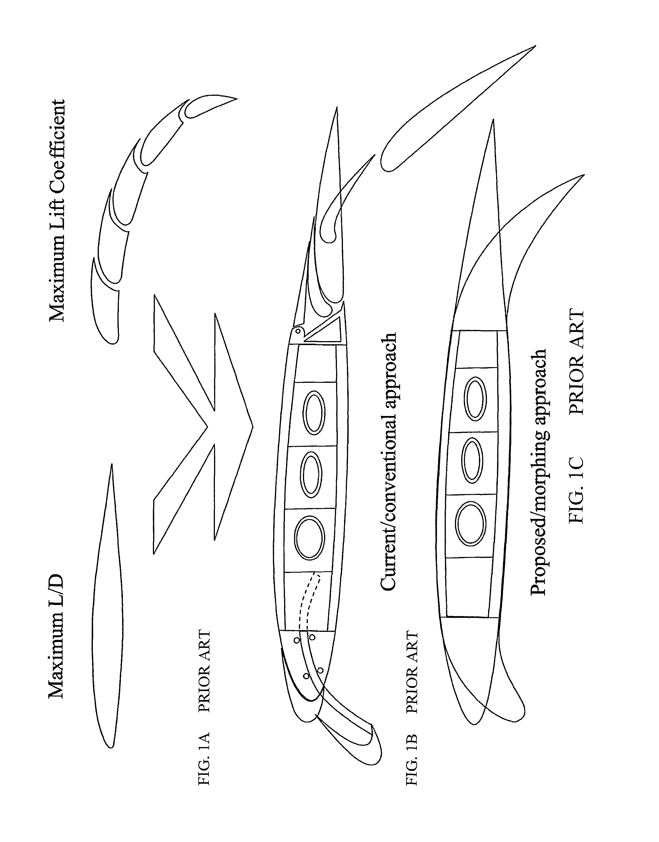
CROSS-REFERENCE TO RELATED APPLICATION[0001]This application claims the benefit of and priority to U.S. Provisional Patent Application Ser. No. 61 / 229,175, filed Jul. 28, 2009, entitled METHOD AND APPARATUS FOR PRESSURE ADAPTIVE MORPHING STRUCTURE, which application is hereby incorporated by reference in its entirety herein.BACKGROUND OF INVENTION[0002]1. Field of Invention[0003]This invention relates generally to morphing structures, for example aero-structures and, more particularly, to adaptive morphing of aero-structures and other structures.[0004]2. Background Art[0005]This background will utilize by way of example, aero-structures to illustrate a representative need for adaptive deformation or morphing of a structure. However, these background examples are in no way intended to narrow the scope of the present invention.[0006]As an example, during its flight regime, an aircraft's wing needs to accommodate two extreme conditions. During cruise its lift-to-drag ratio should be ma...

Claims


Application Information

Patent Timeline
Patent Type & Authority Patents(United States)
IPC IPC(8): B64C3/46B64C3/52B64C3/44F01B19/00
CPCB64C3/46B64C3/50B64C11/20B64C2003/445Y02T50/145Y02T50/10
Inventor VOS, ROELOFBARRETT, RONALD M.
Owner UNIVERSITY OF KANSAS
Learn More