
Fishing line guide

a fishing line guide and guide technology, applied in fishing, applications, rods, etc., can solve the problems of increasing weight, causing deformation of fishing line guides, and affecting the use of fishing lines, and achieve the effect of increasing weigh

Active Publication Date: 2013-02-05
FUJI IND
View PDF61 Cites 11 Cited by
  • Summary
  • Abstract
  • Description
  • Claims
  • Application Information

AI Technical Summary

Benefits of technology

[0010]Further, since the fishing line guide is generally formed by a material having a high rigidity (for example, a stainless steel), the rod body portion to which the fishing line guide is attached becomes rigid. Accordingly, if a front support leg is provided for avoiding the deformation of the fishing line guide, the rigidity between the front and rear attaching portions becomes further higher, a smooth bend of a whole of the rod body is hard to be obtained in accordance with an enlargement of the degree of inclination of the side support leg to the tip side. Further, a weight is increased, and it gives a feeling of heaviness when handling the rod.
[0025]In the fishing line guide in accordance with the present invention, the degree of inclination of the side support leg to the tip side is made smaller than the conventional one, in spite of the tangle preventing type. Accordingly, it is possible to dissolve the tangle without deteriorating the behavior and use feeling of the fishing rod as well as its strength can be maintained.

Problems solved by technology

On the other hand, since a distance from a root of the side support leg to a top portion of the line guide ring becomes longer, a bending moment applied to the root of the support leg becomes large, and a deformation of the fishing line guide tends to be generated.
Further, a weight is increased, and it gives a feeling of heaviness when handling the rod.

Method used


Image

  • Fishing line guide
  • Fishing line guide
  • Fishing line guide

Examples


Embodiment Construction

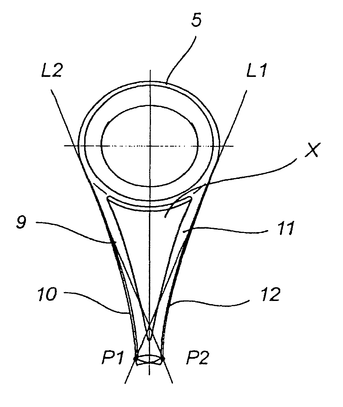
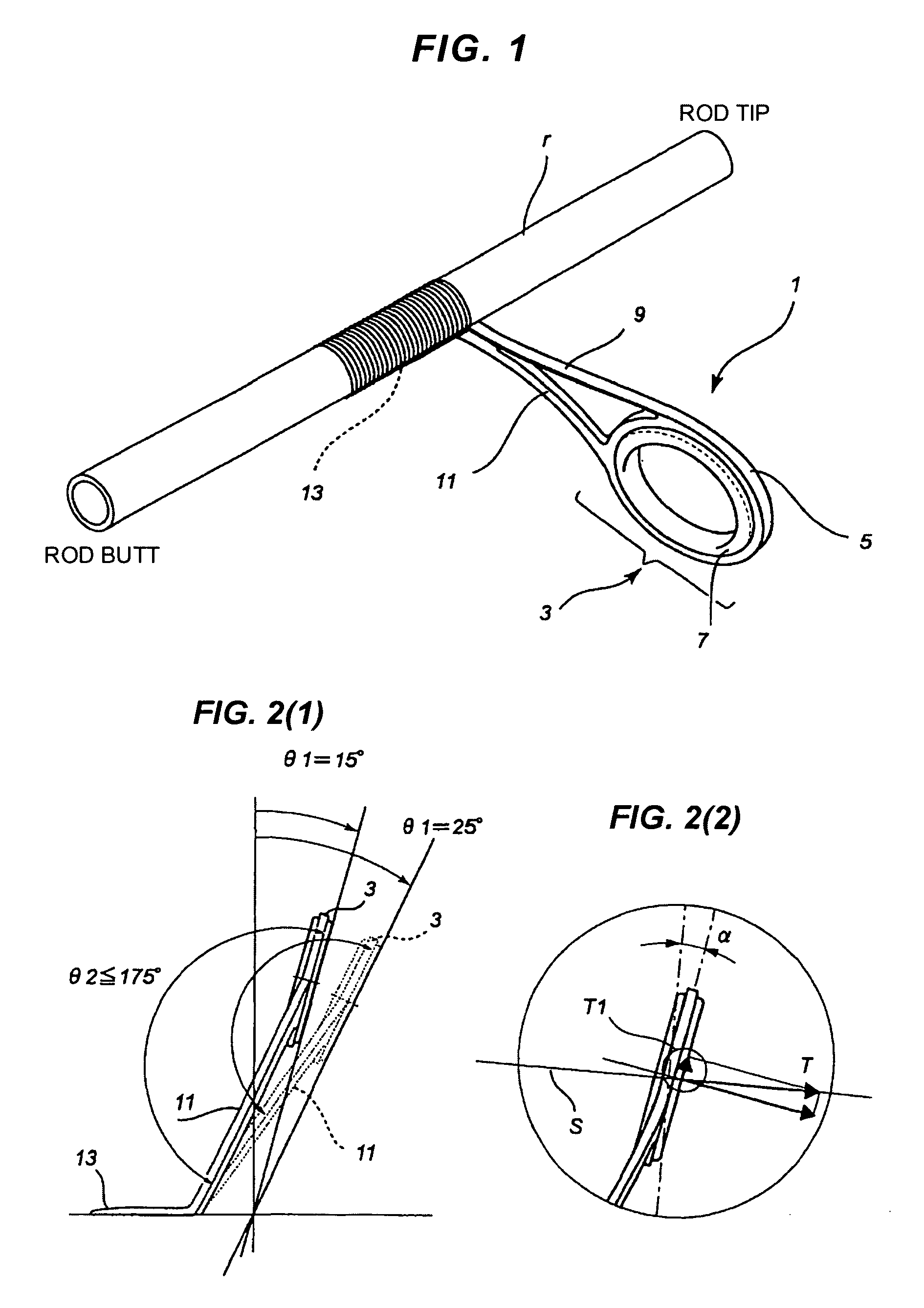
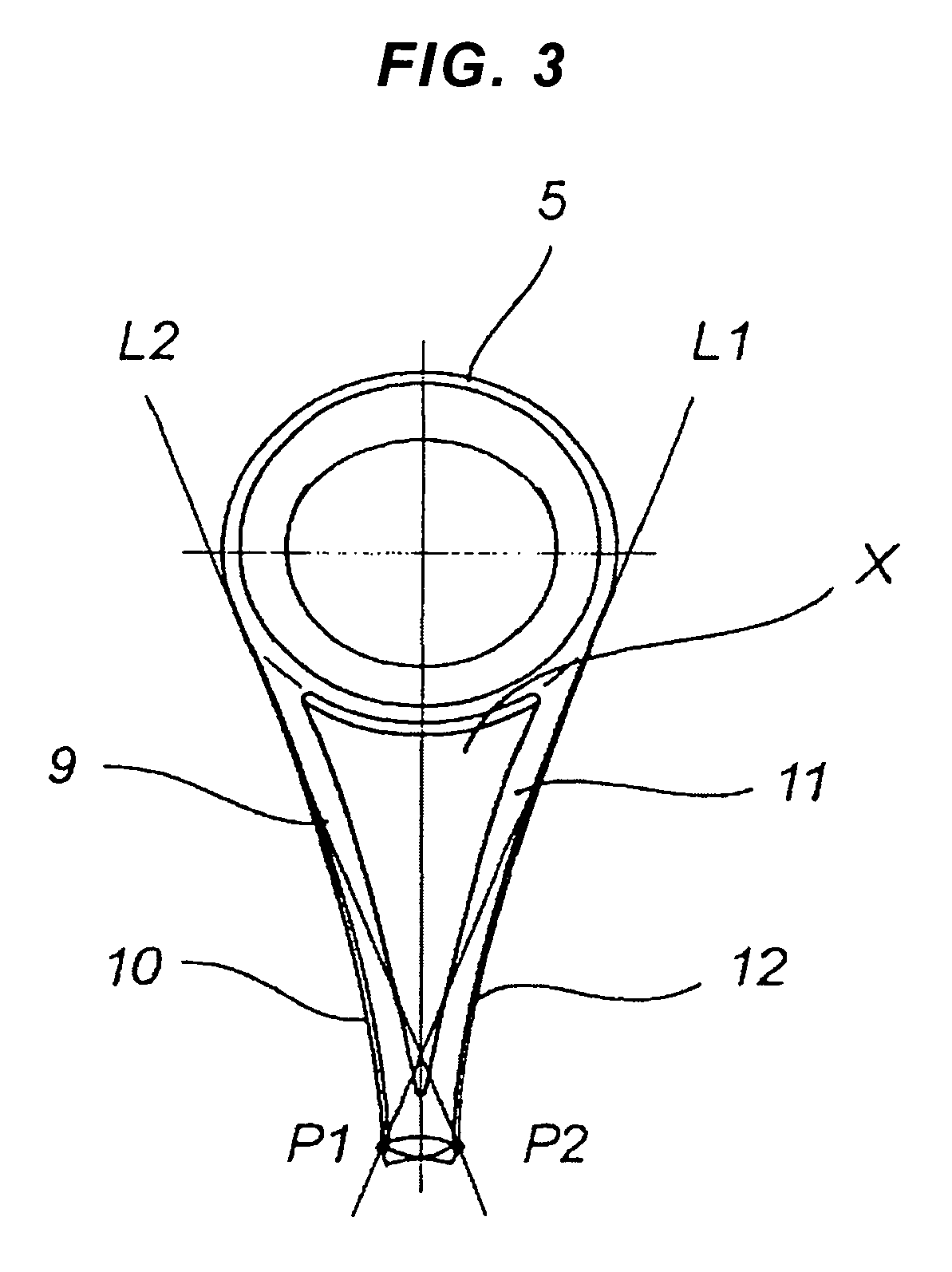
[0039]A description will be given of a fishing line guide 1 in accordance with a first embodiment of the present invention with reference to FIGS. 1 to 13(6). First of all, a description will be schematically given of a whole shape of a fishing line guide 1.

[0040]As shown in FIG. 1, the fishing line guide 1 is formed integrally to have a frame shape from one plane metal plate material. Firstly, it is stamped out to have a predetermined frame shape in accordance with a press work, is further formed in a predetermined three-dimensional shape by applying a bending work, and is provided with a line guide ring 3, a pair of side support legs 9 and 11, and an attaching portion 13.

[0041]The line guide ring 3 is constructed by a hold ring 5, and a guide ring 7 inward fitted thereto. An inner periphery of the hold ring 5 is formed in an approximately complete round shape, and a complete round guide ring 7 is inward fitted to an inner peripheral surface thereof. The guide ring 7 is formed by a...


PUM


Abstract

A fishing line guide having a line guide ring (3) inclined to a tip side, and an angle of junction between the line guide ring (3) and side support legs (9, 11) having an angle smaller at a butt side than at a tip side, and a hook concave portion on which a fishing line is caught so as to be turned back is not formed between the line guide ring (3) and the side support legs (9, 11).

Description

BACKGROUND OF THE INVENTION[0001]1. Field of the Invention[0002]The present invention relates to an outside through fishing line guide.[0003]2. Description of the Conventional Art[0004]In recent years, while a Super braided line (an ultra high molecular weight polyethylene multi filament line) is sold as a fishing line, this Super braided line has an extremely higher strength than a conventional nylon line or fluorocarbon line, and becomes a mainstream of the fishing line. However, since it is a so-called Super braided line as is different from a conventional monofilament line, it has no tension and is extremely flexible. Accordingly, a tangle tends to be generated in comparison with the conventional fishing line, and any tangle prevention measure has been demanded.[0005]Accordingly, the tangle is generated in various fields of the fishing. In addition to a typical case that the fishing line passing through a line guide ring of a fishing line guide goes around a rear side of the lin...

Claims


Application Information

Patent Timeline
Patent Type & Authority Patents(United States)
IPC IPC(8): A01K87/04
CPCA01K87/04
Inventor OMURA, KAZUHITO
Owner FUJI IND
Learn More