Set of mobile necks for inserting into the stem of a hip prosthesis

a hip prosthesis and mobile neck technology, applied in the field of hip prosthesis components, can solve the problems of reducing the height in a way that might not always be acceptable, prohibiting costs, and preventing many people from the chan

Active Publication Date: 2013-01-22
ADLER ORTHO
View PDF10 Cites 13 Cited by
  • Summary
  • Abstract
  • Description
  • Claims
  • Application Information

AI Technical Summary

Benefits of technology

[0011]The inventor of the subject of the present application has, in order to avoid all of the drawbacks set out above, devised a set of necks to meet the requirements of all possible hip prosthesis cases. Thus, using in each case one of the necks taken from the said set, it is possible to have hip prosthesis components at ones disposal that are sufficiently adapted to the anatomical structure of the patient, in such a way as to avoid the kind of large imprecisions that can cause sometimes painful post-operative complications that would lead to the intervention being pronounced a failure.
[0012]The set of the invention, which makes it possible to obtain the functional advantages described above, is composed of a perfectly acceptable minimum number (15) of necks, all different from each other so as to cover with sufficient precision all possible situations, and can therefore be produced without significantly increasing costs compared with the cost of some present-day sets composed of around ten pieces.

Problems solved by technology

The reason for this, of course, is that the desired offset can be obtained by for example reducing the length of the mobile neck, but this would simultaneously reduce the height in a way which might not always be acceptable if the intervention is to be successful.
On the other hand there is no question of supplying “made-to-measure” mobile necks in the sense of having the right length and the right inclination relative to the stem, because in the first place the exact measurements can only be found out during the intervention, and in any case the costs would be prohibitive, precluding many people from the chance of undergoing an intervention to fit a hip prosthesis.

Method used


Image

  • Set of mobile necks for inserting into the stem of a hip prosthesis
  • Set of mobile necks for inserting into the stem of a hip prosthesis
  • Set of mobile necks for inserting into the stem of a hip prosthesis

Examples


Embodiment Construction

[0027]A more detailed description will now be given of an illustrative embodiment of a set according to the invention reference also being made to the accompanying drawing figures.

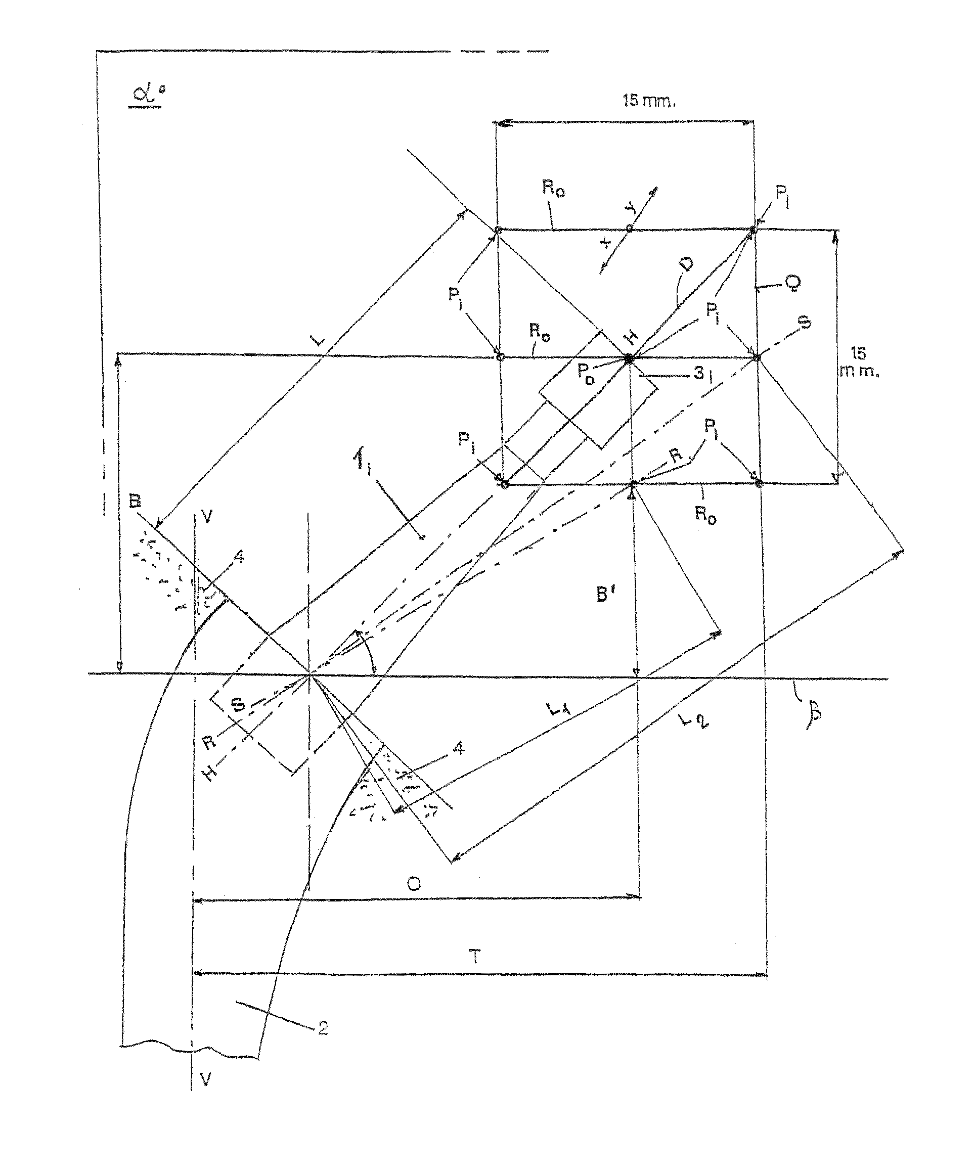
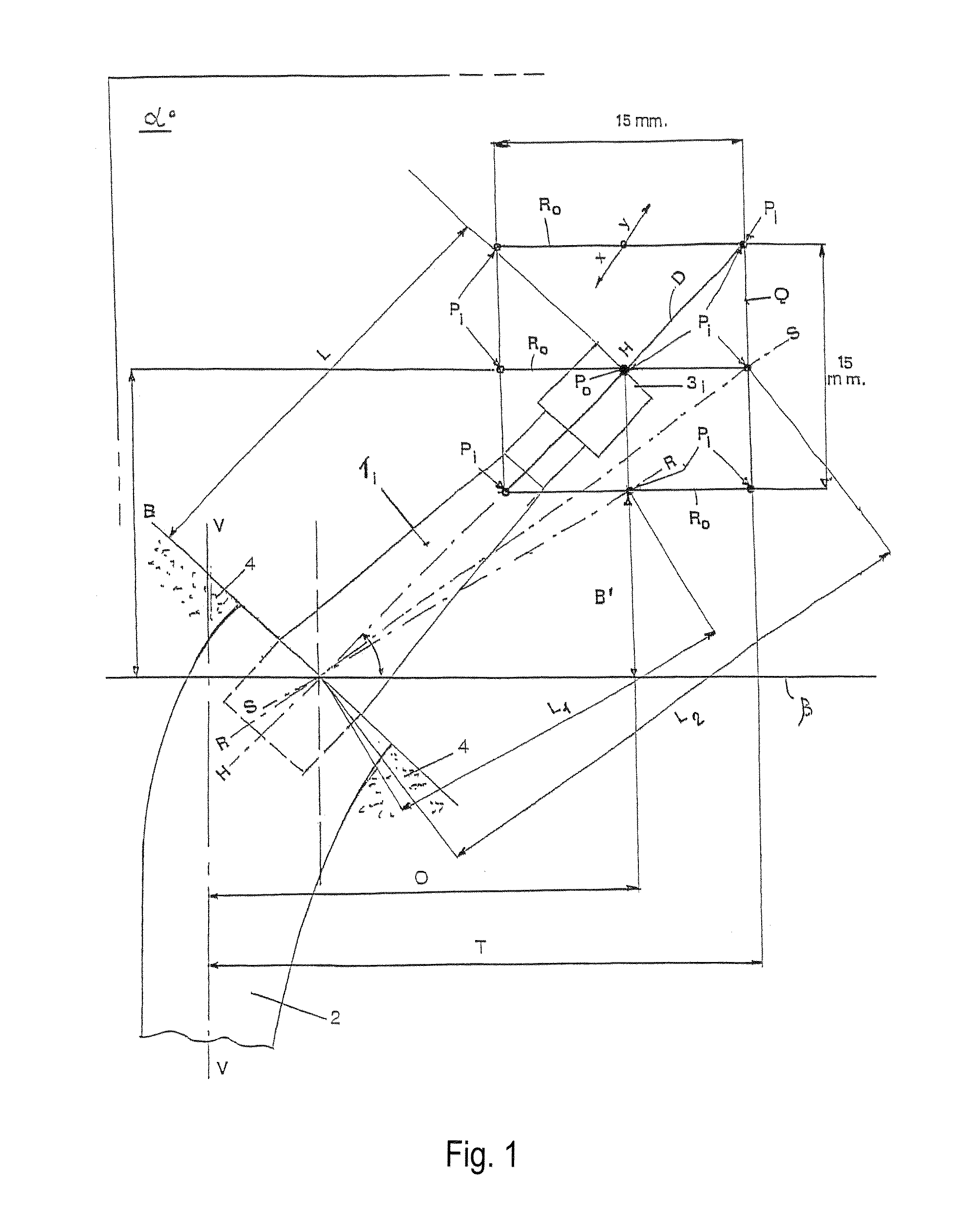
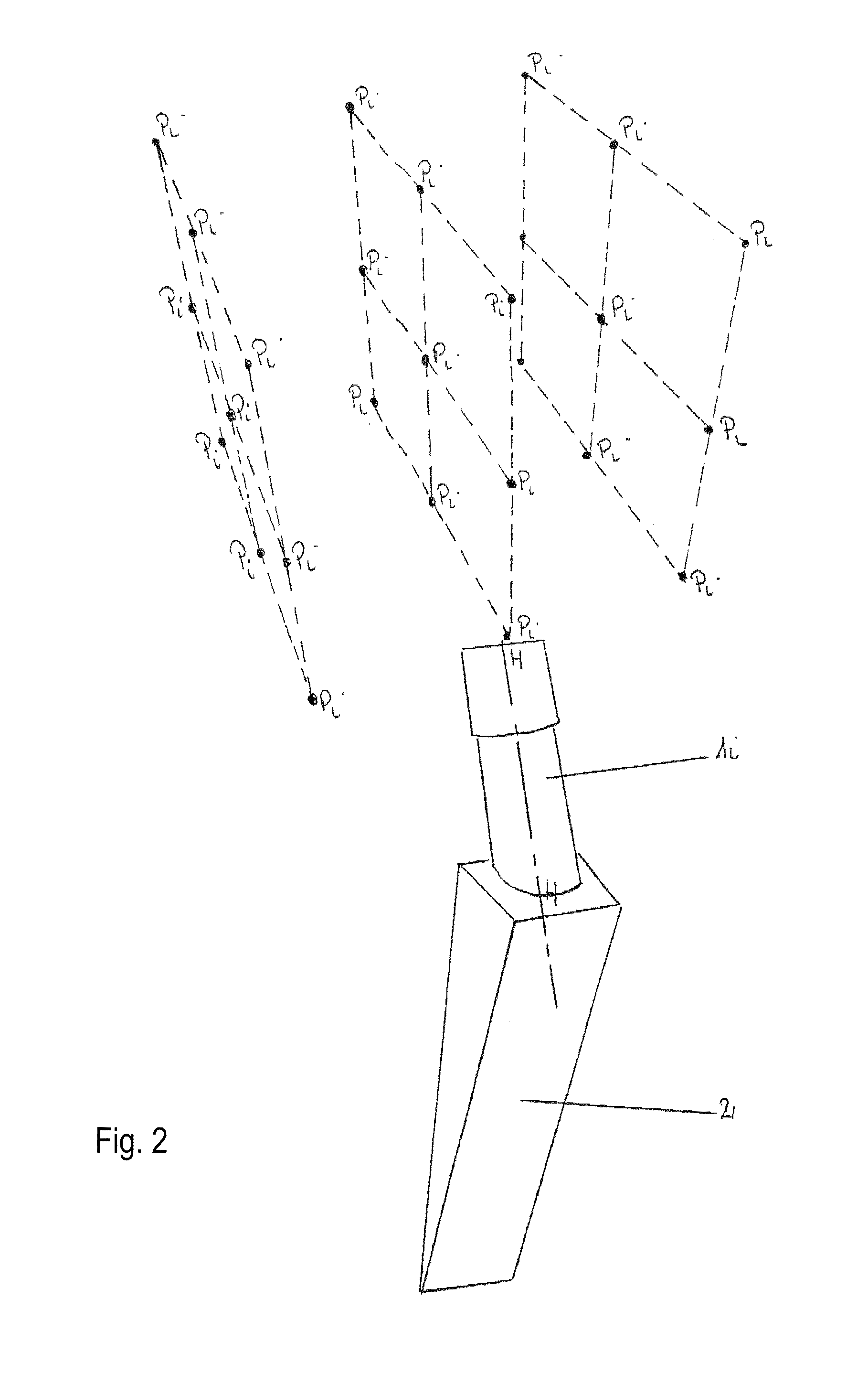
[0028]FIG. 1 is an enlarged diagram illustrating the various possible geometrical characteristics of each neck forming the set. FIG. 2 is another view showing the neck orientation.

[0029]Referring to FIGS. 1 and 2, this shows that nine mutually equidistant points Pi are arranged in threes in three horizontal parallel rows Ro, which are likewise equidistant from each other.

[0030]Part of the stem 2 is inserted into a femur 4, into which there is inserted by known methods one end of a mobile neck 1i belonging to the set of the invention, the free end 3i of which is shaped to allow it to be housed in a spherical head (not shown).

[0031]The free end 3i terminates along the axis H-H of the mobile neck at one of the points Pi, marked Po in the drawing figures, and therefore has a length L and an inclination of 45° ...


PUM


Abstract

A set of mobile necks for inserting into the stem (2) of a hip prosthesis, in which the mobile necks are produced with different inclinations and lengths in such a way that their free ends (3i), when inserted in the stem, terminate at nine mutually equidistant points (Pi) arranged in three parallel horizontal rows (R0) in such a way that the lines joining the outermost points delineate a square (Q), the length of whose sides is approximately 15 mm, the diagonal (D) of this square coinciding with the axis (H-H) of a mobile neck (1) set at a neutral inclination, that is neither varus nor valgus, with respect to a plane (ss) essentially perpendicular to the axis of the abovementioned stem (2).

Description

CROSS REFERENCE TO RELATED APPLICATIONS[0001]This application is a continuation-in-part of application Ser. No. 10 / 547,150, filed Aug. 26, 2005, which is the 35 U.S.C. §371 national stage of PCT / IB2004 / 002874, filed Sep. 2, 2004, which claims priority of Swiss application no. 1599 / 03, filed on Sep. 18, 2003. The entire contents of each of the above-identified applications are hereby incorporated by reference. Any disclaimer that may have occurred during prosecution of the above referenced applications is hereby expressly disclaimed.BACKGROUND OF THE INVENTION[0002]1. Field of the Invention[0003]The present application relates to the technological sector of the component parts of a hip prosthesis.[0004]2. Description of the Related Art[0005]As is known to those skilled in the art, these component parts consist of a stem, which is fitted into the cavity of the femur, and into this stem is inserted a “neck” (referred to as mobile in the sense that it does not form an integral whole wit...

Claims


Application Information

Patent Timeline
Patent Type & Authority Patents(United States)
IPC IPC(8): A61F2/36
CPCA61F2/3609A61F2/3662A61F2002/30341A61F2002/30538A61F2002/30616A61F2002/3625A61F2002/365A61F2002/3652A61F2002/3656A61F2220/0033A61F2250/0006A61F2002/30339A61F2002/3054
Inventor RAGBIR, SHEILA
Owner ADLER ORTHO
Why Eureka
Try Eureka