
Oil recovery method and apparatus

a recovery method and oil technology, applied in the field of oil recovery methods and equipment, can solve the problems of difficulty in obtaining high-quality oil from drill cuttings, etc., to achieve efficient recovery of high-quality oil, promote mixing and heat transfer, and increase surface area

Active Publication Date: 2013-01-22
RACIONAL ENERGY & ENVIRONMENT
View PDF57 Cites 14 Cited by
  • Summary
  • Abstract
  • Description
  • Claims
  • Application Information

AI Technical Summary

Problems solved by technology

The physical nature of the oil based drill cuttings (OBDC) complicates the recovery of oil.
Numerous attempts have been tried to recover or remove a high quality oil from the drill cuttings with limited success.
For example, the industry has had a long-felt need to address one or more of the following problems in the prior art OBDC treatment processes: the quantity of oil recovered may be very low and / or the residual oil remaining in the solids too high; the process or processing equipment may require excessive amounts of energy, require a long treatment time, require large equipment not easily transported to a processing site, require excessive capital for expensive equipment, or entail excessive risk of explosion or other hazards; or the treated drill cuttings may have a pH less than 6 or more than 8, i.e., the drill cuttings may be too acidic or especially too alkaline for environmental disposal; or the quality of the oil obtained may not be suitable for re-use in drilling muds, especially synthetic grade muds requiring one or more of a higher flash point, viscosity and / or VI, and a lower pour point, specific gravity, aromatics content and / or functional group content, relative to the oil typically present in and / or recovered from an OBDC treatment process.

Method used


Image

  • Oil recovery method and apparatus
  • Oil recovery method and apparatus
  • Oil recovery method and apparatus

Examples


examples

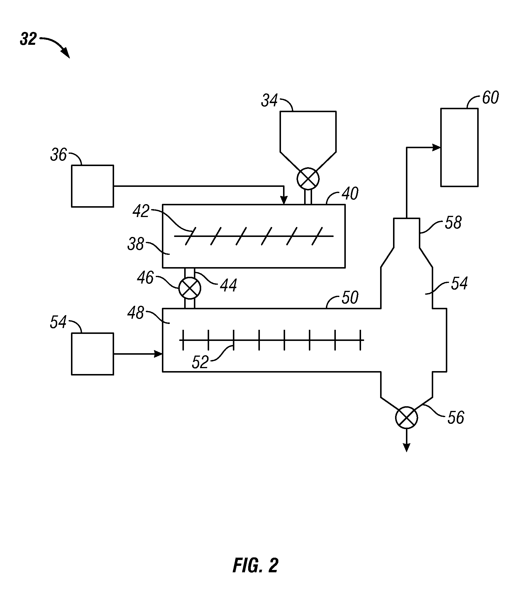
[0113]The peptizing step in one embodiment is important to the success of the instant process. In Comparative Example 1, an oil based drill cuttings (OBDC) substrate having 11 wt % water, 9.3 wt % oil, and 79.7 wt % solids was treated according to a comparative process using a lab scale setup including a peptizer, an agitated direct thermal desorber, and a cyclone, but without adding any acid to the peptizer The desorber agitator speed was 115 rpm with a tip speed of 1.1 m / s and the residence time of the combustion effluent gas was about 3 seconds (27.7 m / min). The material from the peptizer was heated in the thermal desorber under turbulent conditions using co-current fuel-rich combustion effluent gas at 920° C. to obtain an outlet temperature of 220° C., which was subject to cyclone separation to remove entrained solids, followed by condensation and decanting to recover oil and water streams. The substrate and liquid and solids product streams were measured and analyzed for oil, w...


PUM

PropertyMeasurementUnit
temperatureaaaaaaaaaa

Abstract

A method and apparatus for recovering oil from oil-containing sorbents, such as drill cuttings obtained from drilling with an oil-based mud. The method includes peptizing the substrate with an acid reagent and direct thermal desorption with combustion effluent gases at high temperature under turbulent mixing conditions. Another method disclosed includes upgrading the oil in the substrate to improve one or more of the properties of the recovered oil relative to the oil in the substrate, such as, lower aromatics content, lower sulfur content, lower functional group content, higher saturates, higher viscosity, higher viscosity index, and any combination thereof. The apparatus provides for efficient recovery of oil from the substrate with a short residence time, high throughput, low residual oil content in the treated solids and / or high percentage of oil recovery. The apparatus may be transported to a remote location for on-site treatment of drill cuttings or other oil-containing solids.

Description

CROSS REFERENCE TO RELATED APPLICATION[0001]This application claims priority benefit to U.S. Provisional Application No. 61 / 408,494, filed Oct. 29, 2010, which is herein incorporated by reference in its entirety.FIELD OF THE INVENTION[0002]This disclosure relates to the recovery of oil from solid substrates, and also to the upgrading of oil in a heterogeneous chemical-thermal desorption system.[0003]The composition of many oil-based drilling muds typically includes the following compounds: (1) bentonite; (2) barite; (3) kerosene, diesel or other oil; (4) polymers; (5) sodium, calcium and potassium chlorides; (6) lime; and (7) water (invert emulsion). The inverse emulsion generally uses more oil than water. As used herein, the term “oil-based mud” also includes synthetic muds that are sometimes classified separately even though they contain appreciable amounts of hydrocarbons.[0004]Conventional oil based drilling fluids may use oil containing as much as 30% aromatics or more, such as...

Claims


Application Information

Patent Timeline
Patent Type & Authority Patents(United States)
IPC IPC(8): C09K8/02C10G7/00
CPCC09K3/32C10G1/002C10G1/02C09K8/34C10G1/045C10G2300/201C10G2300/302E21B21/063
Inventor PEREZ-CORDOVA, RAMON
Owner RACIONAL ENERGY & ENVIRONMENT
Learn More