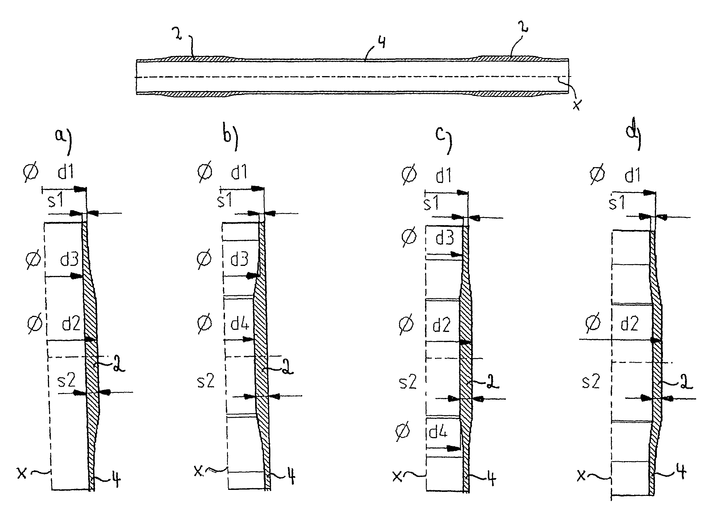
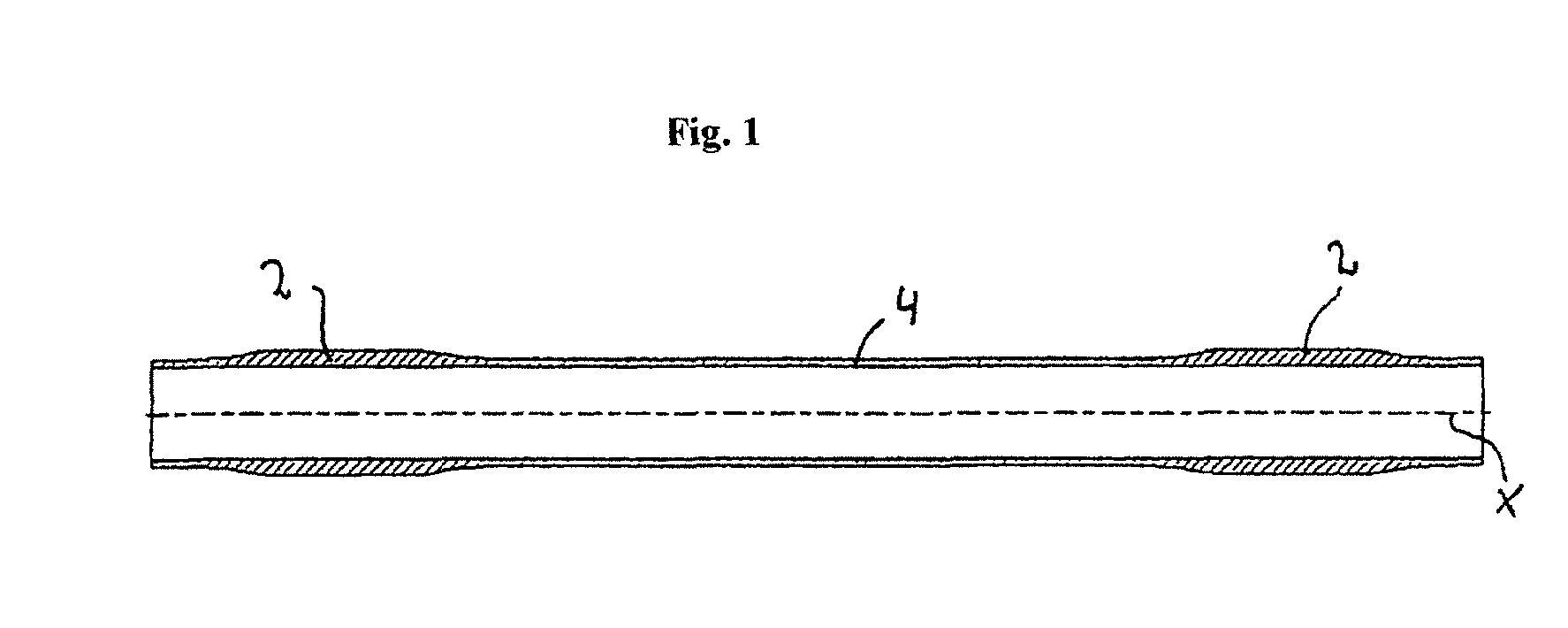
[0005]The axle body has a center section and at least one adjoining receiving section, the receiving section being adjacent to the center section in the axial direction. In particular, the receiving section constitutes an end face or distal end of the axle body. Advisedly, the axle body has a center section with a receiving section arranged at both of its opposite end faces, so that the receiving sections constitute the ends of the axle body. The receiving section serves to receive an axle guide, which can preferably be designed as a longitudinal or transverse link or functional control arm. The axle guide serves in particular to link the vehicle axle or the axle body to a vehicle frame. For this, the axle guide is arranged or received or fastened on the receiving section, while the fastening can be direct or indirect. In its center section, the axle body preferably has an essentially constant wall thickness. In other words, the wall thickness, defined as the difference between outer radius and inner radius (or outer diameter and inner diameter), is essentially constant or equal in the center section of the axle body in the axial direction or longitudinal direction. Of course, any slight deviations in the manufacturing tolerances of the axle pipe should be disregarded as they relate to the constant wall thickness, as this center section has a generally uniform tolerance throughout. Accordingly, the axle body in the receiving section likewise has a wall thickness which is defined in similar manner by the difference between outer radius and inner radius (or outer diameter and inner diameter) of the axle pipe. However, this is greater than the wall thickness of the center section of the axle body. Given the theoretical assumption that an encircling weld produced directly on the axle results in a strength loss of around 50%, it is thus possible to offset this strength loss by the geometrical shape of the axle. Due to the partial thickening of the wall thickness of the axle pipe in the region of the weld between axle guide and axle body, it is thus advantageously possible to do without extra structural parts, such as shells (wraps) to which the axle guide is generally welded, since the axle guide can be welded directly on the axle body. This results, in particular, in cost and weight advantages, so that the production process can be substantially simplified. The axle body, in particular in the region of the receiving section and / or the center section, has a wall thickness which is essentially constant in the radial or circumferential direction. Thus, in other words, the axle body has a wall of essentially equal thickness in the radial or circumferential direction, any manufacturing tolerances or deviations in small regions (such as the corner or edge regions of a quadrangular cross section) being left out of consideration.
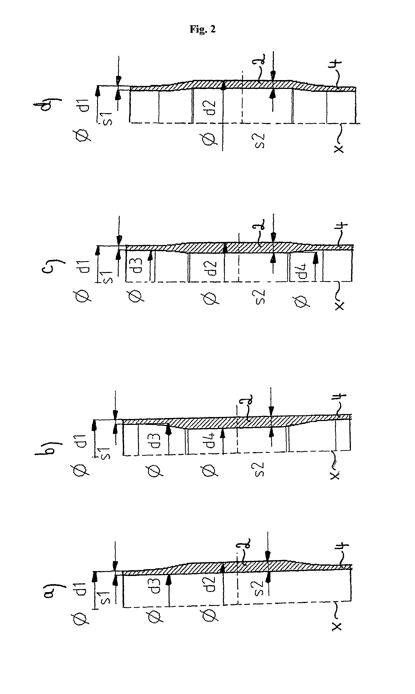
[0008]Thus, one can provide an axle body having an outer diameter which is larger in the receiving section than in the center region and an inner diameter which is smaller in the receiving section than in the center section, so that a thickening or increased wall thickness is provided overall in both directions (inward and outward) in the receiving section.
[0011]In one preferred embodiment, the receiving section has a first and a second connection region for arrangement of regions of the axle guide, on which the weld between axle guide and axle body is formed (such as side walls of the axle guide), as well as a center region lying in between, while the wall thickness of the first and second connection regions is larger than the wall thickness of the center section and the center region. Advisedly, the axle body has a receiving section at either end of the center section, so that one axle guide can be arranged at the two end regions. The axle guide is generally designed to have a box shape and thus it has two spaced-apart side walls with a continuous opening, through which the axle body or the receiving section of the axle body stretches. The axle body is welded all around to the side walls of the axle guide. Consequently, the first and second connection regions are spaced apart from each other so that they are flush with the side walls of the axle guide. Of course, the axle guide need not necessarily have side walls, so that the advantageous linking of the axle guide to the axle body generally occurs at those connection regions where the weld is provided between axle guide and axle body. Advantageously, the wall thickness of the first and second connection region is greater than the wall thickness of the center region of the receiving section and / or the center section. Thus, the center region of the receiving section can have essentially the same wall thickness as the center section of the axle body. It is noted that the center region can also have a different wall thickness, preferably a somewhat larger wall thickness than that of the center section. Such a configuration provides an advantageous weight savings and a simplification of the forming process due to the lesser degree of forming.
[0013]Moreover, preferably the wall thickness of the first connection region is larger than that of the second connection region, and the first connection region is preferably toward the center of the axle. In particular, the axle body can be fashioned such that the outer diameter or radius of the first connection region is larger than that of the second connection region. The first connection region is advantageously toward or closer to the center of the axle or the center section, whereas the second connection region is consequently further away from the center section or the center of the axle. This is especially advantageous, since an optimal force pathway is created between axle guide and axle body, since the larger forces occurring at the side facing the middle of the axle will follow an optimized contour. Furthermore, this prevents transposing or twisting of an axle guide with such a shape.
[0017]Furthermore, according to the invention, there is provided a running gear design, especially for a commercial vehicle, comprising an axle body fashioned as an axle pipe and at least one axle guide, wherein the axle body has a center section and at least one adjoining receiving section to receive the axle guide, wherein the axle body in the center section has an essentially constant wall thickness, and the axle body in the receiving section has at least in some regions a wall thickness which is greater than the wall thickness of the center section. Thus, advantageously, a running gear arrangement is provided in which the axle guide can be arranged or fastened especially advantageously on the receiving section. This fastening can occur, in particular, directly or without an intermediate element (such as a wrap), and an encircling weld between the axle guide and the receiving section of the axle body does not weaken it, due to the increased wall thickness in this region.
