Automotive rotary electric machine
a rotary electric machine and electric motor technology, applied in the direction of dynamo-electric components, electric apparatus casings/cabinets/drawers, association for rectification, etc., can solve the problem of easy electrical contact failure between the connecting wire and the rear bracket, increased risk of screw rotation in the loosening direction, and excessive increases in electrical contact resistance. , to suppress the effect of contact failur
- Summary
- Abstract
- Description
- Claims
- Application Information
AI Technical Summary
Benefits of technology
Problems solved by technology
Method used
Image

Examples
embodiment 1
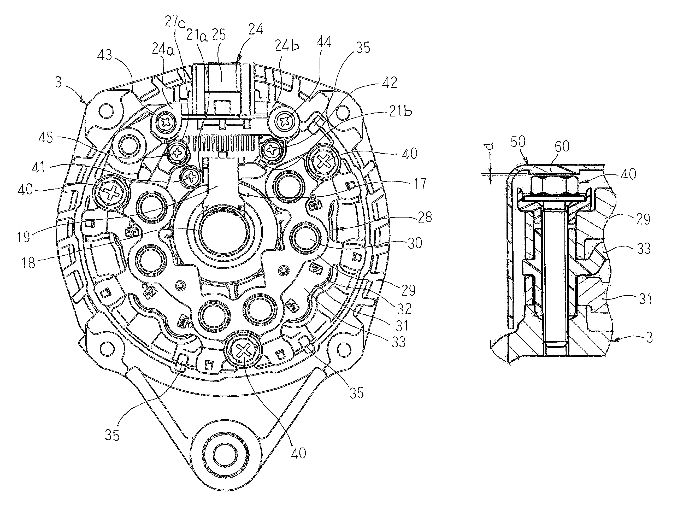
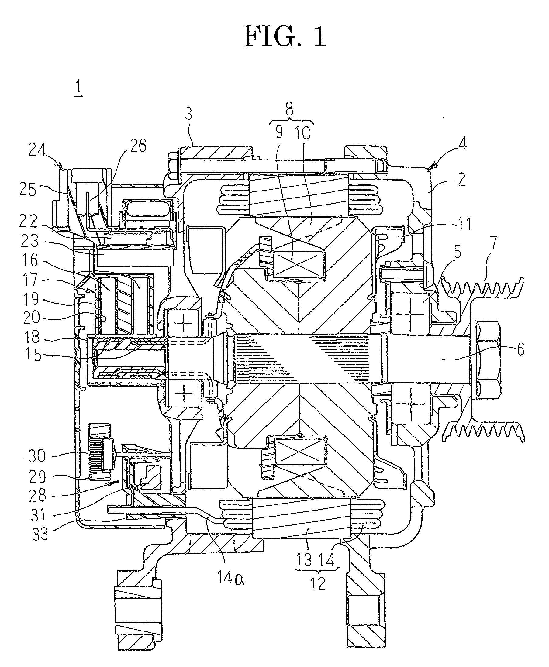
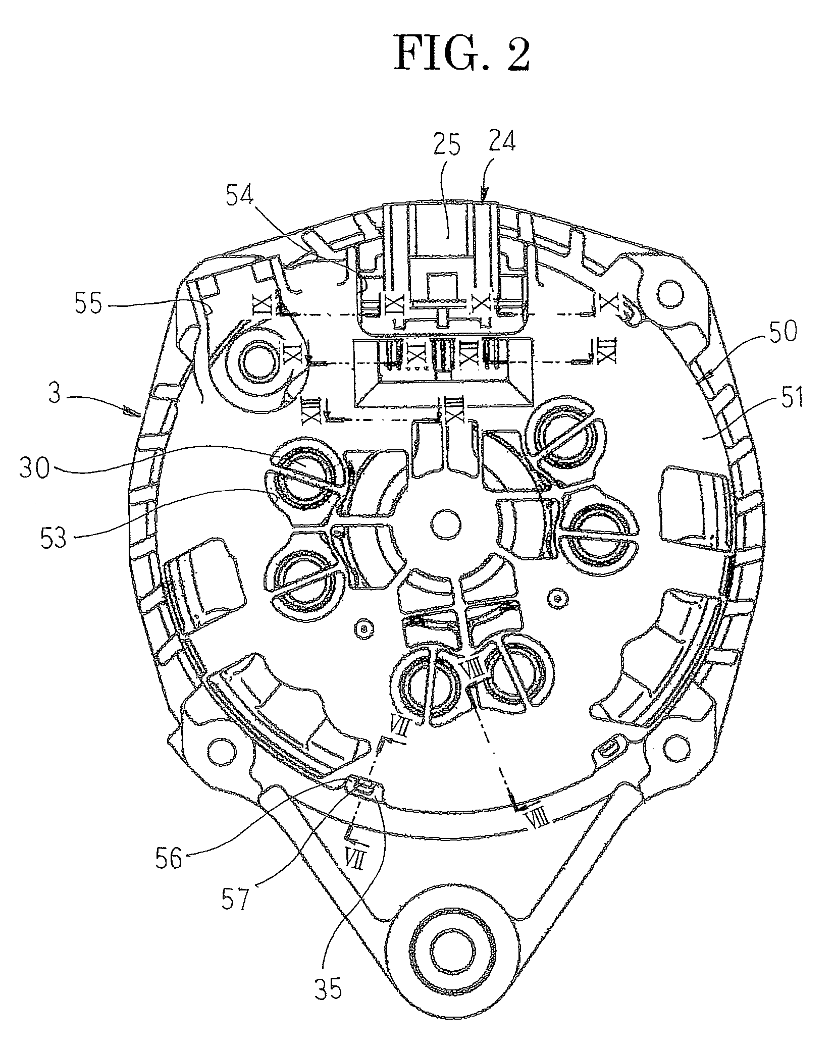
[0025]FIG. 1 is a longitudinal cross section that shows an automotive alternator according to Embodiment 1 of the present invention, FIG. 2 is a rear-end end elevation that shows the automotive alternator according to Embodiment 1 of the present invention, FIG. 3 is a rear-end end elevation that shows a state before mounting a protective cover in the automotive alternator according to Embodiment 1 of the present invention, FIG. 4 is a front elevation that shows the protective cover in the automotive alternator according to Embodiment 1 of the present invention, FIG. 5 is a rear elevation that shows the protective cover in the automotive alternator according to Embodiment 1 of the present invention, FIG. 6 is a partial perspective that explains a method for mounting the protective cover in the automotive alternator according to Embodiment 1 of the present invention, FIG. 7 is a cross section that is taken along Line VII-VII in FIG. 2 so as to be viewed in the direction of the arrows,...
embodiment 2
[0053]FIG. 14 is a rear-end end elevation that shows a mounted state of a protective cover in an automotive alternator according to Embodiment 2 of the present invention.
[0054]In FIG. 14, a salient portion 66 is disposed so as to project centrally from an apex portion of a fifth screw loosening restricting lug 64. The salient portion 66 is configured so as to be inserted into a cross recess 46 that is formed on an apex portion of a head portion of a voltage regulator fixing second screw 44 when a protective cover 50A is mounted to a rear bracket 3.
[0055]Salient portions 66 are also disposed so as to project centrally from apex portions of first through fourth, and sixth screw loosening restricting lugs 60 through 63, and 65 and are configured so as to be inserted into cross recesses 46 that are formed on apex portions of the head portions of rectifying apparatus fixing screws 40, a second brush holder fixing screw 42, voltage regulator fixing first and second screws 43 and 44, and a...
PUM
 Abstract
Description
Claims
Application Information
 - R&D
- Intellectual Property
- Life Sciences
- Materials
- Tech Scout
- Unparalleled Data Quality
- Higher Quality Content
- 60% Fewer Hallucinations
Browse by: Latest US Patents, China's latest patents, Technical Efficacy Thesaurus, Application Domain, Technology Topic, Popular Technical Reports.
© 2025 PatSnap. All rights reserved.Legal|Privacy policy|Modern Slavery Act Transparency Statement|Sitemap|About US| Contact US: help@patsnap.com