
Flow component for medical infusion/transfusion lines

a flow component and flow line technology, applied in the field of medical infusion/transfusion lines, can solve the problems of needle risk, high risk, and possible flexure, and achieve the effect of facilitating centering and small amount of effor

Active Publication Date: 2013-01-08
IND BORLA
View PDF14 Cites 9 Cited by
  • Summary
  • Abstract
  • Description
  • Claims
  • Application Information

AI Technical Summary

Benefits of technology

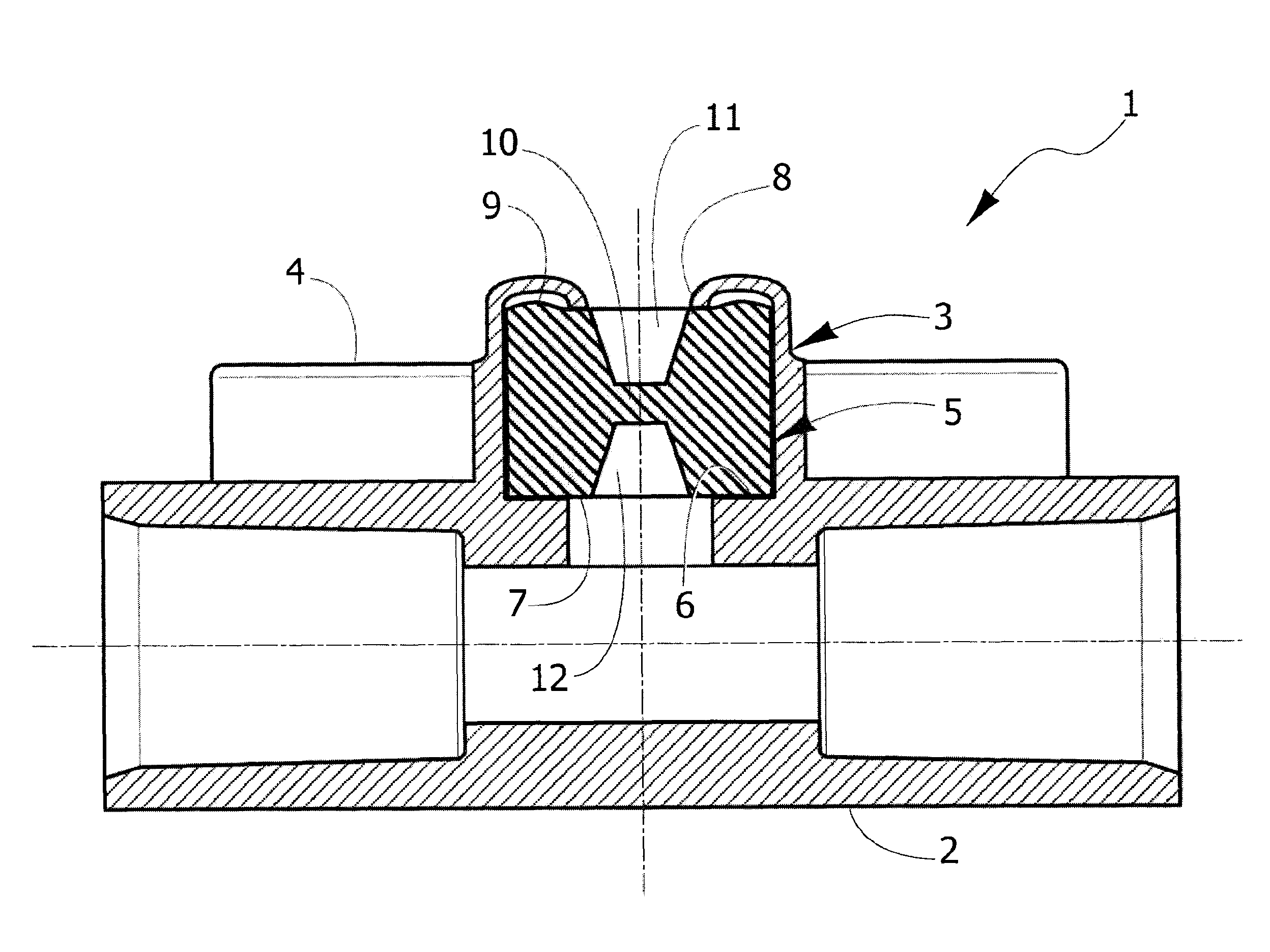
[0007]Thanks to this arrangement, traversal of the elastic sealing element by the fluid introducer requires, in use, an appreciably smaller amount of effort on the part of the operator, without on the other hand affecting in any way the features of sealing of the inlet connector by the elastic element. Furthermore, the axial cavity of the elastic sealing element facilitates centering of the fluid introducer, thus favouring proper traversal of the diaphragm of small thickness of the elastic element and reducing the risk of said introducer erroneously intercepting the wall of the inlet connector, thus getting stuck.
[0010]This characteristic facilitates assembly of the flow component, given that the elastic sealing element has in this case a symmetrical conformation that enables insertion and locking thereof within the inlet connector indifferently in a first position or else in a second position turned over through 180°.

Problems solved by technology

In use, the perforation of the elastic sealing element and its traversal by the needle of the fluid introducer is inconvenient, in so far as it requires the operator to exert a certain amount of effort, and also involves the risk of the needle, on the tip of which a certain load is applied, possibly undergoing flexure until it bends or even breaks, instead of perforating the elastic sealing element.
This risk is particularly high in the case where the needle of the fluid introducer is pushed by the operator against the elastic sealing element, instead of in a position where it is properly centred and aligned with its axis, in an off-centre condition and / or with a more or less accentuated angle with respect to the axis of the inlet connector.
In such an eventuality, the tip of the needle, instead of traversing the elastic sealing element completely, can intercept the wall of the inlet connector, thus preventing proper injection of fluid by the introducer to the main duct of the flow component.

Method used


Image

  • Flow component for medical infusion/transfusion lines
  • Flow component for medical infusion/transfusion lines
  • Flow component for medical infusion/transfusion lines

Examples


Embodiment Construction

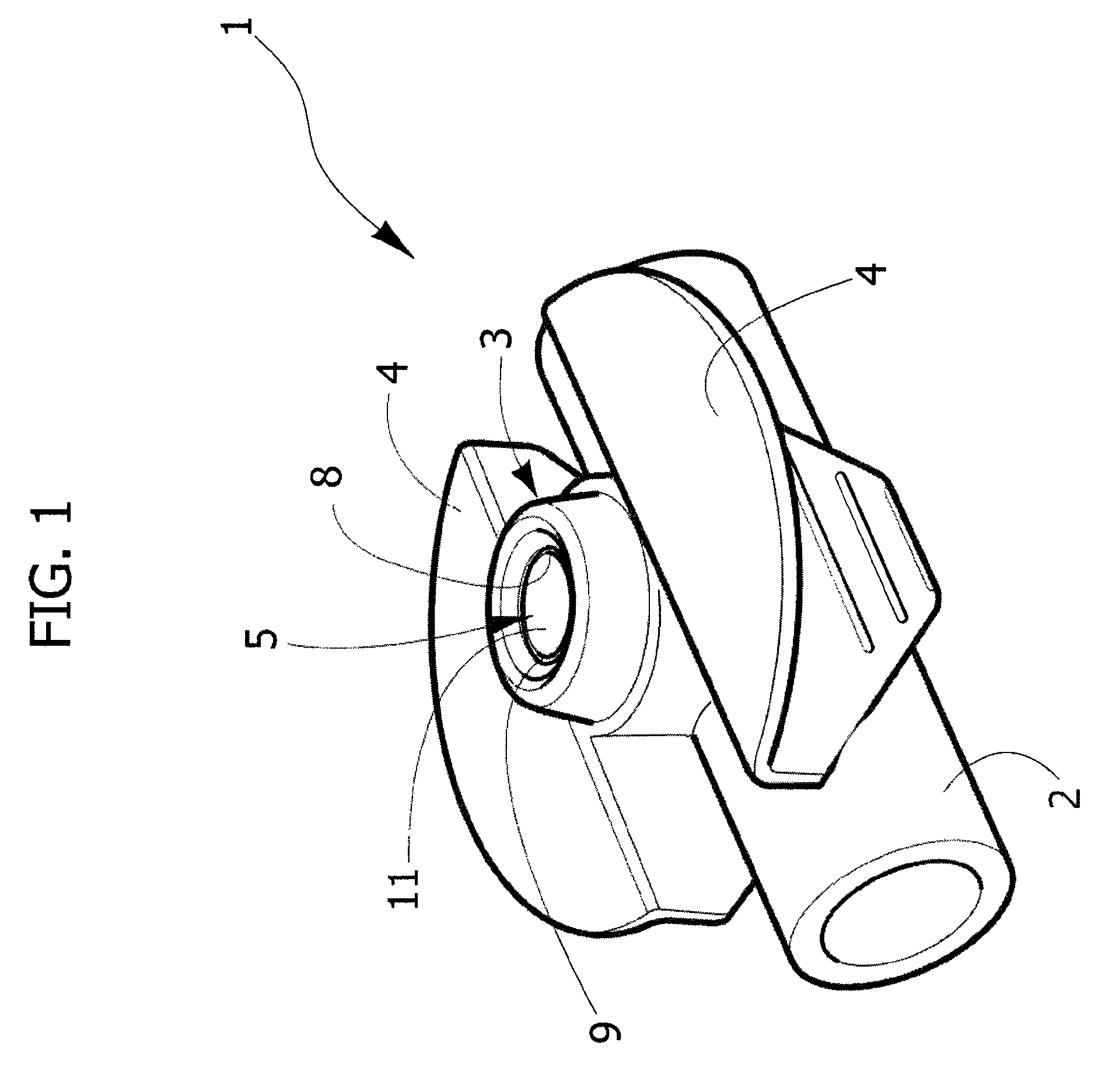
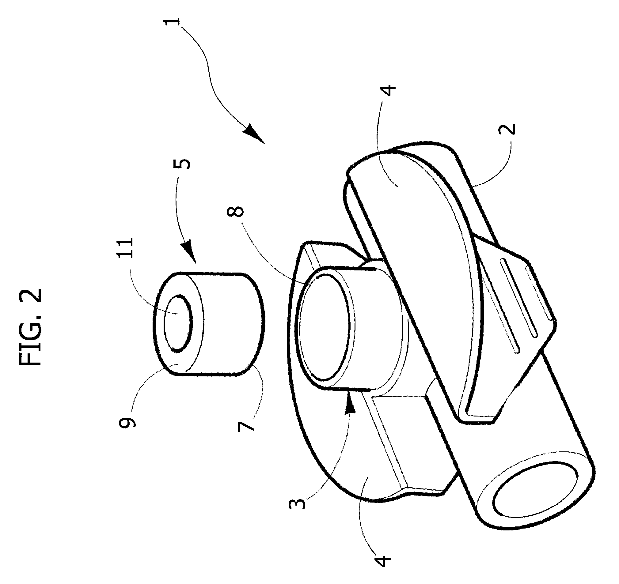
[0017]With reference initially to FIGS. 1 to 3, designated as a whole by 1 is a flow component according to the invention, applicable to a medical infusion / transfusion line and consisting of a so-called T-shaped or cross-shaped needle point. The flow component 1 is formed by a tubular body that basically comprises a main duct 2, designed in use to be traversed by a flow of a primary liquid, and a side tubular inlet connector 3 directed perpendicularly, i.e., radially with respect to the duct 2, in a substantially median area of the latter, for introduction of a secondary liquid into it. A pair of gripping and protection tabs 4 project from the outer surface of the duct 2 on opposite sides with respect to the inlet connector 3.

[0018]Housed in a fluid-tight way within the inlet connector 3 is an elastic sealing element 5 having a generally cylindrical shape, typically made of a soft elastomeric material, such as silicone rubber and the like. Said elastic sealing element 5 is blocked a...


PUM


Abstract

A flow component for medical infusion / transfusion lines includes a tubular body having a side inlet connector, housed in a fluid-tight way in which is an elastic sealing element that can be traversed by a fluid introducer. The elastic sealing element has at least one axial cavity, which defines, for traversal by the fluid introducer, a diaphragm of small thickness.

Description

CROSS-REFERENCE TO RELATED APPLICATIONS[0001]This application claims priority from Italian patent application Serial No. TO2007A000473, filed on Jun. 29, 2007, the entirety of which is hereby incorporated by reference.FIELD OF THE INVENTION[0002]The present invention relates in general to medical infusion / transfusion lines. More in particular, the subject of the invention is a flow component for medical lines of this sort, which comprises a tubular body having a side inlet connector, within which a fluid introducer can be inserted and which houses in a fluid-tight way an elastic sealing element that can be traversed by the fluid introducer.STATE OF THE PRIOR ART[0003]In a typical embodiment of a flow component of this type, the tubular body has a general T-shaped or cross-shaped conformation, with a main duct for a primary fluid, converging radially into which is the inlet connector, along with the corresponding elastic sealing element.[0004]The above elastic sealing element traditi...

Claims


Application Information

Patent Timeline
Patent Type & Authority Patents(United States)
IPC IPC(8): A61M25/16A61M5/00A61M5/14A61M39/00A61M25/18A61M39/10A61M25/00A61M39/02
CPCA61M39/045A61M39/10A61M39/26A61M2039/0036
Inventor GUALA, GIANNI
Owner IND BORLA
Learn More