Method and apparatus for locating circuit deviations

a technology of deviation and deviation, applied in the direction of instrumentation, program control, cad circuit design, etc., can solve the problems of large amount of effort and inability to state exactly the site of deviation, and achieve the effect of small effort and high level of accuracy

Active Publication Date: 2006-03-23
SIEMENS ELECTRONIC DESIGN AUTOMATION GMBH
View PDF19 Cites 8 Cited by
  • Summary
  • Abstract
  • Description
  • Claims
  • Application Information

AI Technical Summary

Benefits of technology

[0008] The present invention provides a method and an apparatus for locating circuit deviations, wherein the detection of circuit deviations is achieved with a high level of accuracy and with a small amount of effort.

Problems solved by technology

The previously described approaches for locating circuit deviations have problems, however, in that they require a large amount of effort and that, in some cases, it is not possible to state exactly the site of the deviation.

Method used


Image

  • Method and apparatus for locating circuit deviations
  • Method and apparatus for locating circuit deviations
  • Method and apparatus for locating circuit deviations

Examples


Embodiment Construction

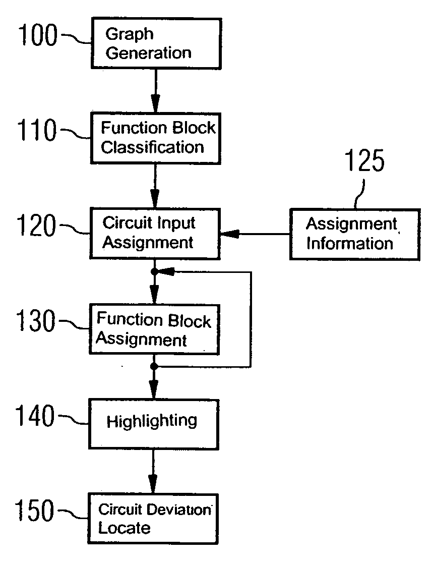
[0036] The following description explains a method for locating circuit deviations of a circuit 10′ in respect of a reference circuit 10. In the example described, the circuit 10′ and the reference circuit 10 are based on a common original circuit design. In particular, the circuit 10′ is a circuit design which has proceeded from the reference circuit 10 in the course of circuit development. In the case of such circuit designs belonging to different development stages, it is necessary for them to be equivalent in respect of their function.

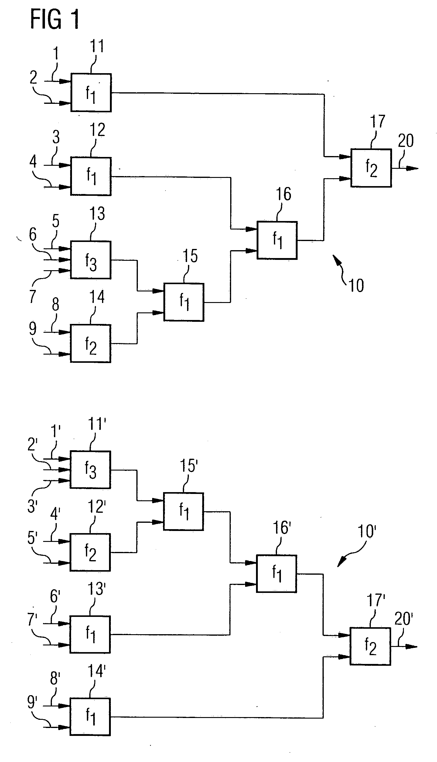
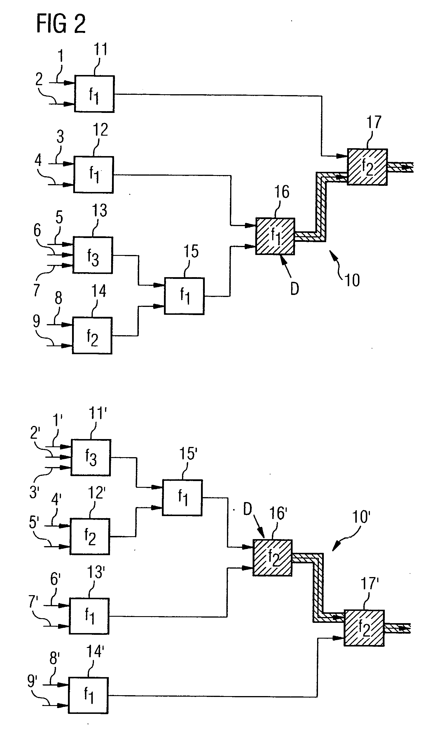
[0037]FIG. 1 shows a circuit 10′ and a reference circuit 10 which are respectively represented in the form of a signal-flow graph. In this case, the circuit 10′ and the reference circuit 10 each comprise function blocks 11′-17′ and 11-17 respectively. In this case, the function blocks 11-17, 11′-17′ respectively have a certain function, this being denoted by the identifier f1, f2 and f3 respectively. These functions are defined, for each of the fu...


PUM


Abstract

A system and method for locating circuit deviations or circuit faults in a circuit in respect of a reference circuit. The circuit and the reference circuit are respectively describable by signal-flow graphs, the signal-flow graphs being composed of a multiplicity of interconnected function blocks. The function blocks of the circuit are first assigned to corresponding function blocks of the reference circuit. There are then ascertained those function blocks of the circuit and of the reference circuit for which assignment has not been possible, and which have disposed upstream in the signal flow at least one function block for which assignment has been possible. The result is a boundary between an assigned and a non-assigned region of the circuit and the reference circuit, respectively. A representation of the circuit and reference circuit is preferably produced in which the regions corresponding to the non-assigned function blocks are highlighted.

Description

PRIORITY CLAIM [0001] This application is a continuation of German Patent Application DE 10 2004 03333.9 filed Jul. 9, 2004, which is incorporated herein by reference. TECHNICAL FIELD [0002] The present invention relates to a method and to an apparatus for locating circuit deviations, wherein a circuit, particularly in the form of an application-specific integrated circuit, is compared with a reference circuit in order to locate in the circuit functional deviations in respect of the reference circuit. BACKGROUND [0003] In the development of so-called ASICs (Application-Specific Integrated Circuits), it is normally necessary to compare different version or optimization statuses of the circuit design with one another. Computer-aided methods, which compare a circuit with a reference circuit in respect of their functional equivalence, are known for this purpose. In this case, the circuit and the reference circuit are typically described by a circuit description language appropriate for ...

Claims


Application Information

Patent Timeline
Patent Type & Authority Applications(United States)
IPC IPC(8): G06F17/50
CPCG06F17/504G06F17/5022G06F30/33G06F30/3323
Inventor HORETH, STEFAN
Owner SIEMENS ELECTRONIC DESIGN AUTOMATION GMBH
Why Eureka
Try Eureka