Multi-piece rim and its attaching/removing method

a multi-piece rim and mounting method technology, applied in the field of multi-piece rims, can solve the problems of large amount of labor, large inability to fit the tires of a large-size construction vehicle or mining vehicle to single-piece rims, etc., and achieve the effect of reducing the number of components to be managed, removing easily and properly

Inactive Publication Date: 2013-01-08
TOPY INDUSTRIES
View PDF28 Cites 11 Cited by
  • Summary
  • Abstract
  • Description
  • Claims
  • Application Information

AI Technical Summary

Benefits of technology

[0077]According to the present invention having the above mentioned constructions, by coupling each end (41a, 42a) of the portions (41, 42) of the lock ring (40) divided in a plurality of portions (for example, divided in two portions) by means of a coupling member (for example, wire 43), by putting the ends (41b, 42b) which are not coupled by means of a coupling member (for example, wire 43) in the gutter band groove (11a), and by pushing them therein, the whole of the lock ring (40) being divided in a plurality of portions is securely fitted in the gutter band groove (11a) and held in the so-called “locked” state.
[0078]Therefore, when the ends (41b, 42b) that are not coupled with the coupling member (43), are coupled (for example, by means of the plate 8 and bolt B2), the tire (6) and multi-piece rim (100) are accurately assembled.
[0079]In case that the lock ring (40) being divided in a plurality of portions (for example, divided in two portions) is fitted in a part of the gutter band groove (11a) (as illustrated in FIGS. 3 and 4), the rim base (1) supports the mass of the lock ring (40). For this reason, although the tire diameter is large and the mass of the lock ring (40) is heavy, a large amount of labor is not required to support the lock ring (40) and a special machine does not need to be prepared.
[0080]Furthermore, by coupling each end (41a, 42a) of the portions of the lock ring (40) divided in a plurality of portions (for example, divided in two portions) by means of a coupling member (for example, wire 43), the portions of the lock ring (40) divided in a plurality of portions (for example, divided in two portions) can be treated as a single member. Therefore, the number of components to be managed can be reduced.
[0081]Furthermore, although the lock ring (40) is divided into a plurality of portions (for example, two portions), fastening work or unfastening work is needed only at one area for one lock ring (40) (see FIGS. 3 to 7). Therefore, it is not necessary to increase a number of tasks being needed to attach and / or to remove the tire (6).
[0082]In addition, the lock ring (40) is divided in a plurality of portions (for example, divided in two portions) can be removed easily and properly from the rim base (1).

Problems solved by technology

Tires for a large-size construction vehicle or mining vehicle are different in rigidity from tires for passenger vehicles, and there are many cases that tires for a large-size construction vehicle or mining vehicle cannot be fitted to single-piece rims.
For example, there are cases that the mass of the lock ring 4 is 50 kg or so, it would be very difficult and require a great deal of labor to place such a heavy lock ring 4 in a prescribed position while holding it against the elastic repulsive force which contracts said lock ring inwardly in the radial direction.
First, in a process for coupling the lock ring, each half portion of the lock ring must be securely fitted in the groove 11a of the gutter band (such that the half portions must be in a “locked” state).
Therefore, a large amount of labor is required to support the lock ring so as to securely fit each half portion of the lock ring in the groove of the gutter band (see 11a in FIG. 14).
Such a prior art reference is useful but does not solve the problem caused by applying a two-piece lock ring as mentioned above.

Method used


Image

  • Multi-piece rim and its attaching/removing method
  • Multi-piece rim and its attaching/removing method
  • Multi-piece rim and its attaching/removing method

Examples


first embodiment

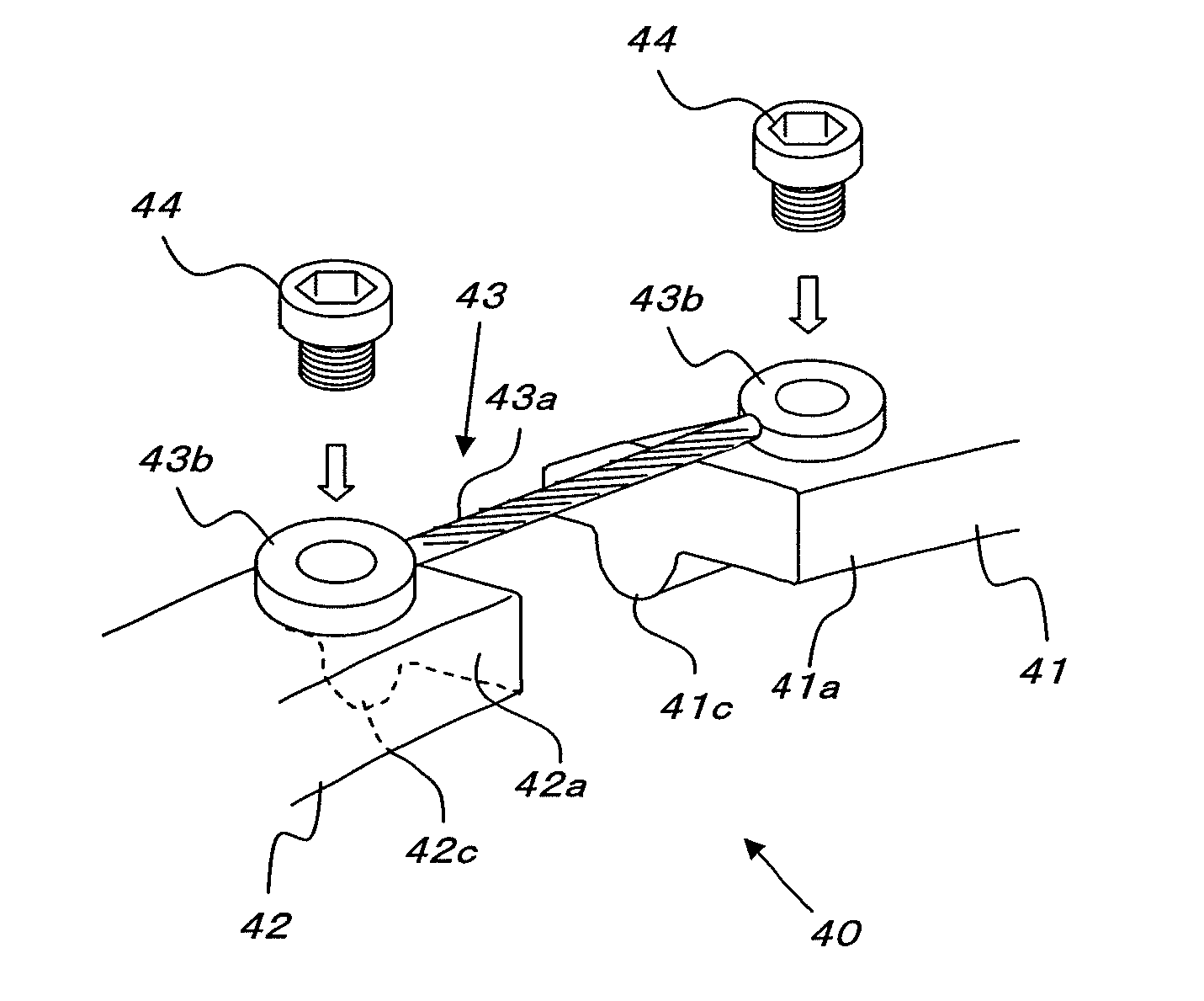
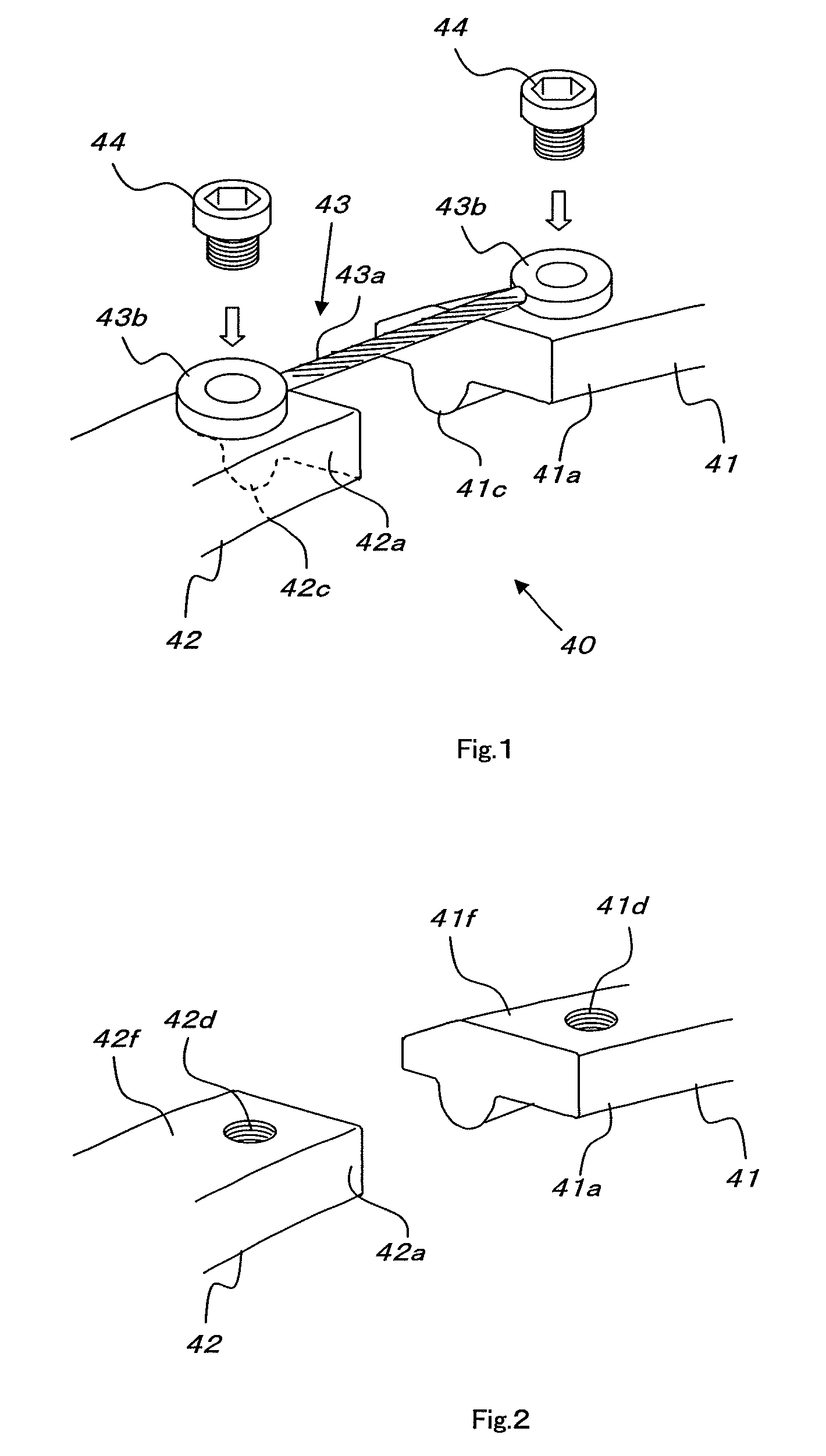
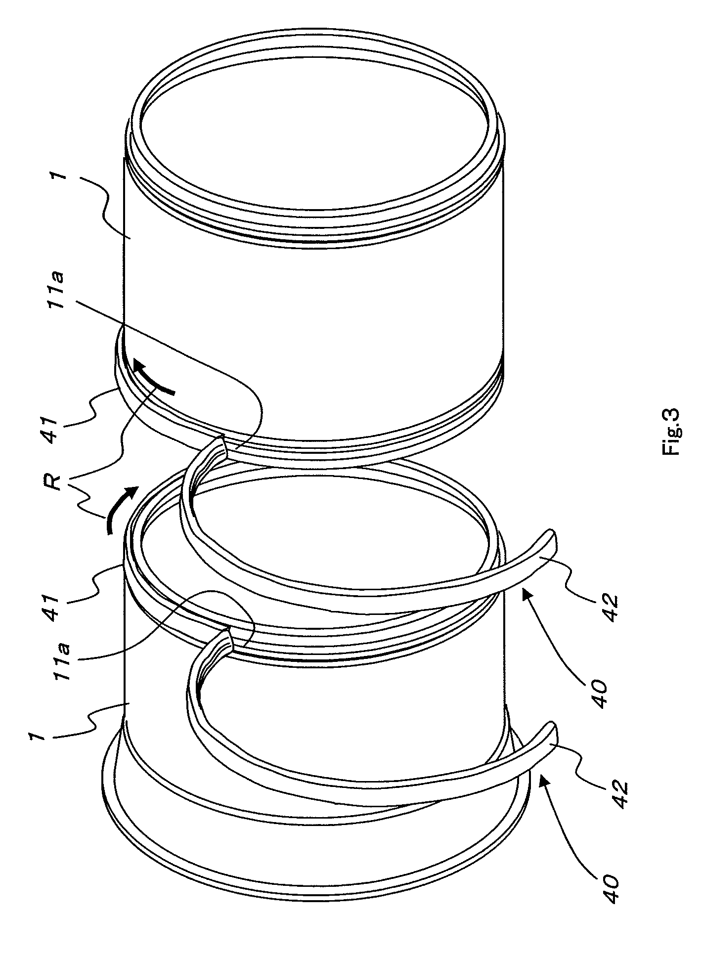
[0126]FIGS. 1 to 7 show the present invention.

[0127]The multi-piece rim according to the first embodiment of the present invention has the same construction as the multi-piece rim shown in FIG. 17 except the lock ring construction. For this reason, the multi-piece rim according to the first embodiment will be first described referring to FIG. 17.

[0128]As illustrated in FIG. 17, the multi-piece rim according to the first embodiment is in the form of the so-called “double tire” in which multi-piece rims are installed on the inner and outer side of the hub of the machine body.

[0129]FIG. 17 shows an example of a rear wheel on the right side of a large-size construction vehicle or mining vehicle having double tires for rear wheels, as seen from behind the machine body.

[0130]In FIG. 17, a flange 51 is formed on the left of a hub 5. The left (inner) multi-piece rim 100J of the double tire is fitted to the flange 51 of the hub 5 with a bolt B.

[0131]Specifically, the hub fitting part 1T of t...


PUM

PropertyMeasurementUnit
massaaaaaaaaaa
tensile forceaaaaaaaaaa
flexibleaaaaaaaaaa

Abstract

It is an object of the present invention to provide a multi-piece rim which does not need much labor for supporting, and does not increase the number of components to be managed and the number of needed tasks.The present invention constructs a lock ring (40) to be fitted in the groove (11a) of a gutter band (11), which ring is divided in a plurality of portions (41, 42) being coupled at each end (41a, 42a) thereof by a flexible coupling member (43). Alternatively, a lock ring (140) is formed into a substantially C-shape being manufactured by cutting a part of a circular ring, and comprises a first portion (141) wherein a length of a chord at the cut portion is substantially equal to the diametral of a hub, and a second portion (142) having a shape corresponding to the cut portion of a circular ring in the first portion.

Description

BACKGROUND OF THE INVENTION[0001]1. Field of the Invention[0002]The present invention relates to a multi-piece rim attached to a tire for a construction vehicle or a mining vehicle, and more particularly, for a large-size construction vehicle or mining vehicle.[0003]2. Background Art[0004]Tires for a large-size construction vehicle or mining vehicle are different in rigidity from tires for passenger vehicles, and there are many cases that tires for a large-size construction vehicle or mining vehicle cannot be fitted to single-piece rims. For this reason, multi-piece rims are often used for tires for a large-size construction vehicle or mining vehicle.[0005]The construction of such a multi-piece rim is shown in FIG. 14.[0006]In FIG. 14, a multi-piece rim 100J has a rim base 1, left and right side rings 2, a bead seat band 3, and a lock ring 4.[0007]A range near an end of the rim base 1 where the lock ring 4 is located (right end in FIG. 14) is a so-called gutter band 11. A back flang...

Claims


Application Information

Patent Timeline
Patent Type & Authority Patents(United States)
IPC IPC(8): B60B25/04
CPCB60B11/06B60B25/06B60B25/20Y10T29/49526Y10T29/49815
Inventor OBA, KENTARONAKAMURA, YUKIOHIGASHINO, YOSHIYUKI
Owner TOPY INDUSTRIES
Why Eureka
Try Eureka