
System for automatically gathering battery information

a battery information and automatic collection technology, applied in the field of storage batteries, can solve the problems of inaccurate battery test, improper battery charging, and bad battery determination

Active Publication Date: 2013-01-01
MIDTRONICS
View PDF726 Cites 90 Cited by
  • Summary
  • Abstract
  • Description
  • Claims
  • Application Information

AI Technical Summary

Problems solved by technology

If the voltage is below a certain threshold, the battery is determined to be bad.
Reliance on user entry of battery information may result in incorrect information being entered, which in turn can result in inaccurate battery test results or improper charging of the battery.

Method used


Image

  • System for automatically gathering battery information
  • System for automatically gathering battery information
  • System for automatically gathering battery information

Examples


Embodiment Construction

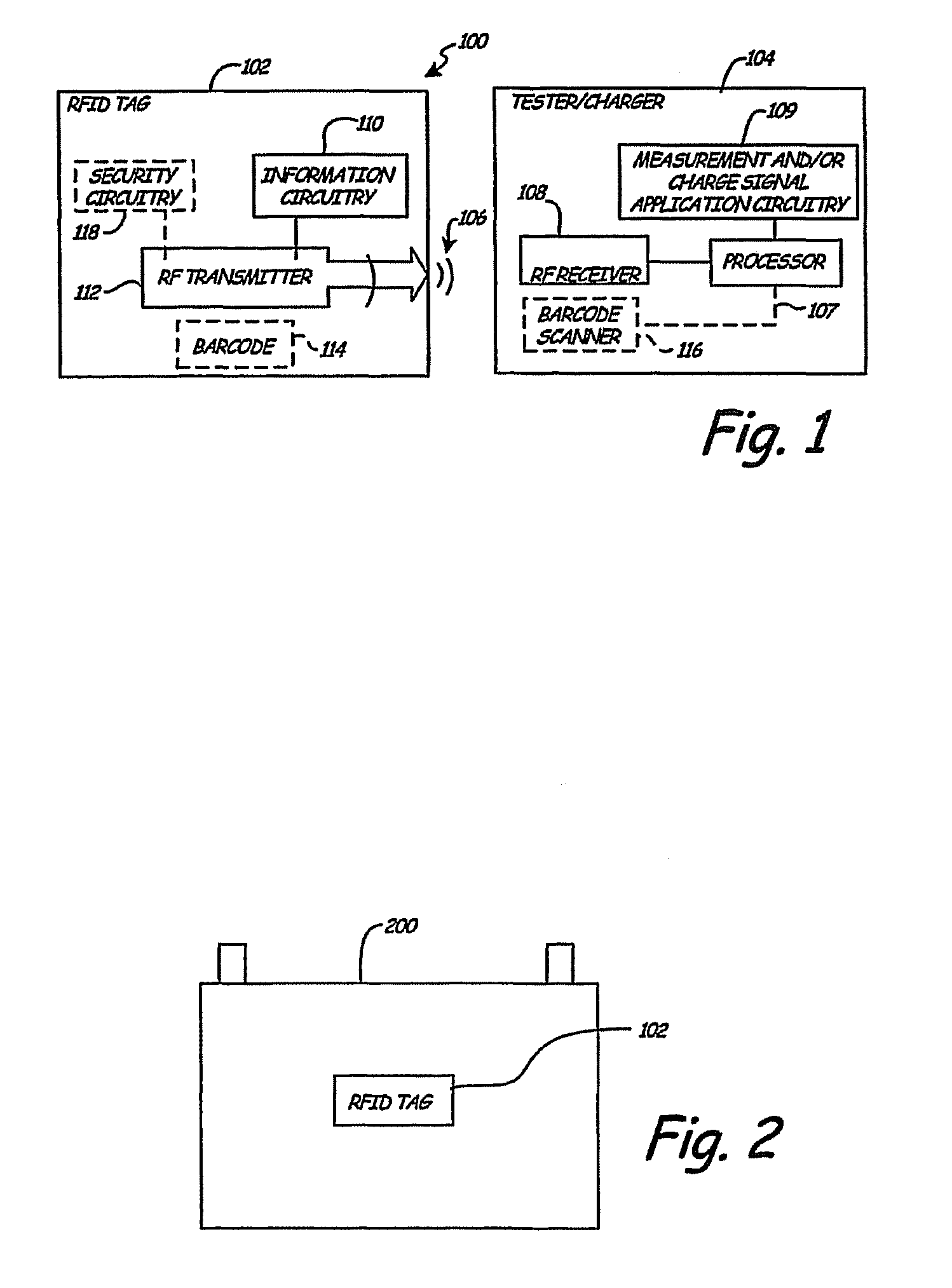
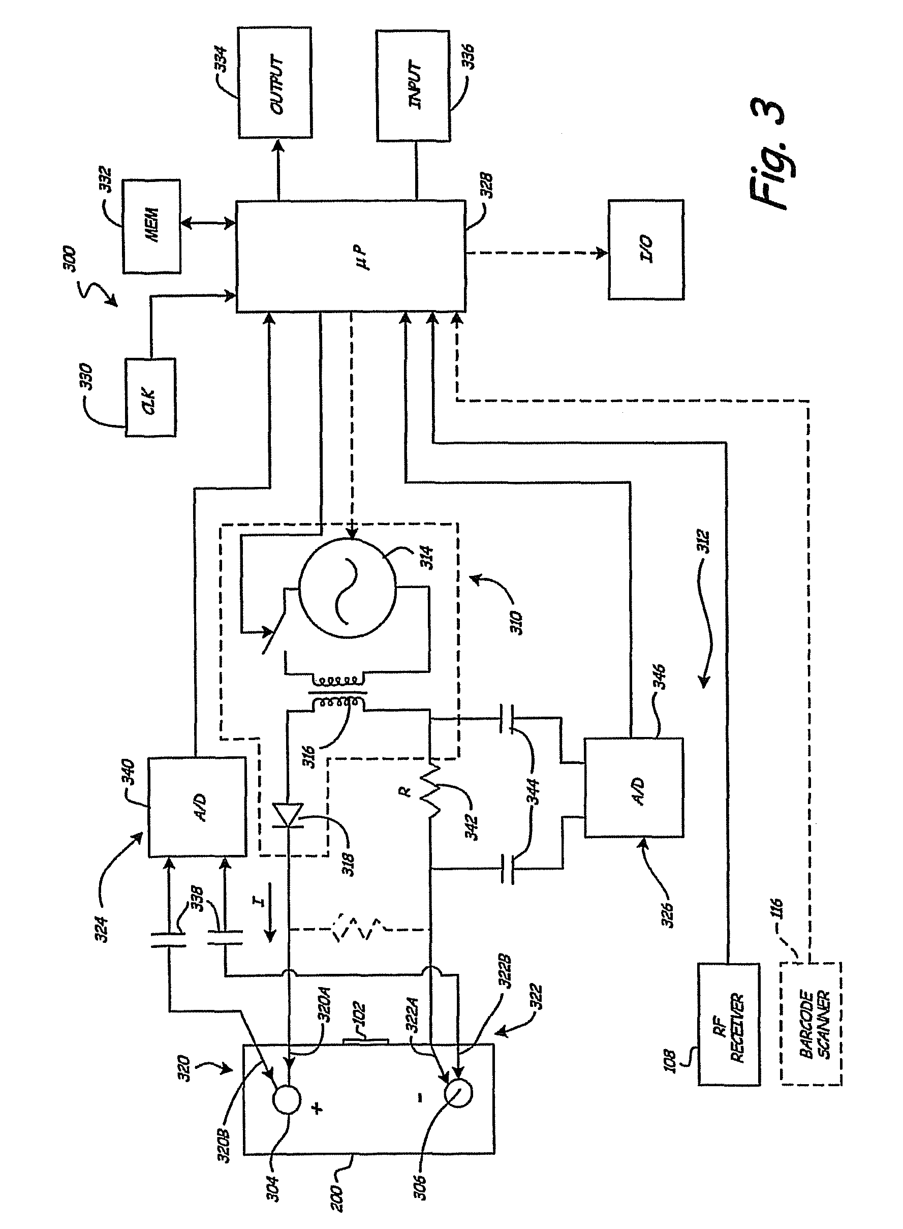
[0018]FIG. 1 is a simplified block diagram of a battery testing / charging system 100 in accordance with an embodiment of the present invention. System 100 includes a radio frequency identification (RFID) tag 102, which can be affixed to a battery (such as 200 (FIG. 2)). RFID tag 102 is configured to transmit stored battery information in the form of RF signals 106. System 100 also includes a battery tester / charger 104 having an embedded / integrated radio frequency (RF) receiver 108, which is configured to receive the transmitted battery information from RF tag 102 when battery tester / charger 104 is proximate RF tag 102. The battery information, which is automatically received by RF receiver 108, is utilized by processor 107 and measurement and / or charge signal application circuitry 109 to test / charge the battery (such as 200 (FIG. 2)). Thus, system 100 overcomes problems with prior art testers / chargers that, in general, require a tester / charger user to enter battery information with t...


PUM

PropertyMeasurementUnit
voltage potentialaaaaaaaaaa
total voltageaaaaaaaaaa
timeaaaaaaaaaa

Abstract

A method that includes affixing a radio frequency identification tag on a storage battery at a battery manufacturing plant. The method also includes storing battery manufacturing information into the radio frequency identification tag at the battery manufacturing plant. The battery manufacturing information includes a battery algorithm suitable for use in testing the storage battery.

Description

[0001]The present application is a Continuation-In-Part of and claims priority of U.S. patent application Ser. No. 11 / 207,419, filed Aug. 19, 2005, now abandoned which is based on and claims the benefit of U.S. provisional patent application Ser. No. 60 / 603,078, filed Aug. 20, 2004, the contents of which are hereby incorporated by reference in their entirety.CROSS REFERENCE TO RELATED APPLICATIONS[0002]Reference is made to co-pending and commonly assigned U.S. patent application Ser. No. 12 / 416,445, filed Apr. 1, 2009, entitled “SIMPLIFICATION OF INVENTORY MANAGEMENT,” and to co-pending and commonly assigned U.S. patent application Ser. No. 12 / 416,453, filed Apr. 1, 2009, entitled “INTEGRATED TAG READER AND ENVIRONMENT SENSOR,” the contents of which are hereby incorporated by reference in their entirety.BACKGROUND OF THE INVENTION[0003]The present invention relates to storage batteries. More specifically, the present invention relates to a system for automatically gathering battery ...

Claims


Application Information

Patent Timeline
Patent Type & Authority Patents(United States)
IPC IPC(8): H02J7/00G01N27/416
CPCG06Q99/00H01M2/0267G06K19/0723H01M10/488H02J7/0009H01M2/0275G01R31/3648H02J2007/0098H02J7/00043H01M10/4257H02J7/00047Y02E60/10
Inventor BERTNESS, KEVIN I.PHILBROOK, JOHN S.
Owner MIDTRONICS
Learn More