
Analog MPPT circuit for photovoltaic power plant

a photovoltaic power plant and analog technology, applied in the direction of constant-current supply dc circuit, constant-current supply ac circuit, electric variable regulation, etc., can solve the problems of low energy conversion efficiency, low cost of photovoltaic power plants, and few methods of tracking mpp

Active Publication Date: 2012-12-25
STMICROELECTRONICS SRL
View PDF11 Cites 21 Cited by
  • Summary
  • Abstract
  • Description
  • Claims
  • Application Information

AI Technical Summary

Benefits of technology

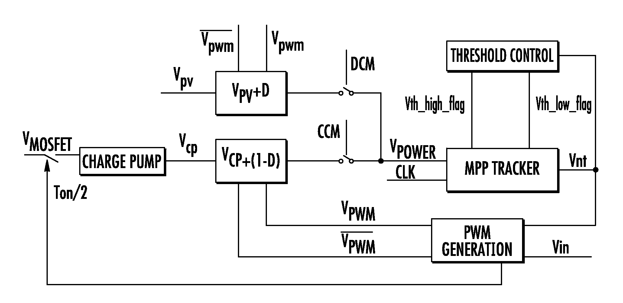
The patent describes a method for maximizing the power output of a photovoltaic power plant using a DC-DC converter and a power switch driven by a PWM control signal. The method can be implemented using low-cost analog circuits and does not require any analog-to-digital conversion or digital processing. The method involves detecting the mode of operation of the converter, multiplying the current output voltage by a time ratio, sampling the voltage drop on the power switch, and comparing the resulting signals to a delayed replica or time averaged value. The method can be used with a single panel or multiple panels of photovoltaic cells. The patent also describes an analog circuit that can force the duty cycle of the PWM control signal to invert the sign of variation for maximum power point tracking. The technical effect of the patent is to provide a simple and cost-effective method for maximizing the power output of photovoltaic power plants using a DC-DC converter and a power switch driven by a PWM control signal.

Problems solved by technology

The cost of photovoltaic (PV) power plants is still high while energy conversion efficiency remains low.
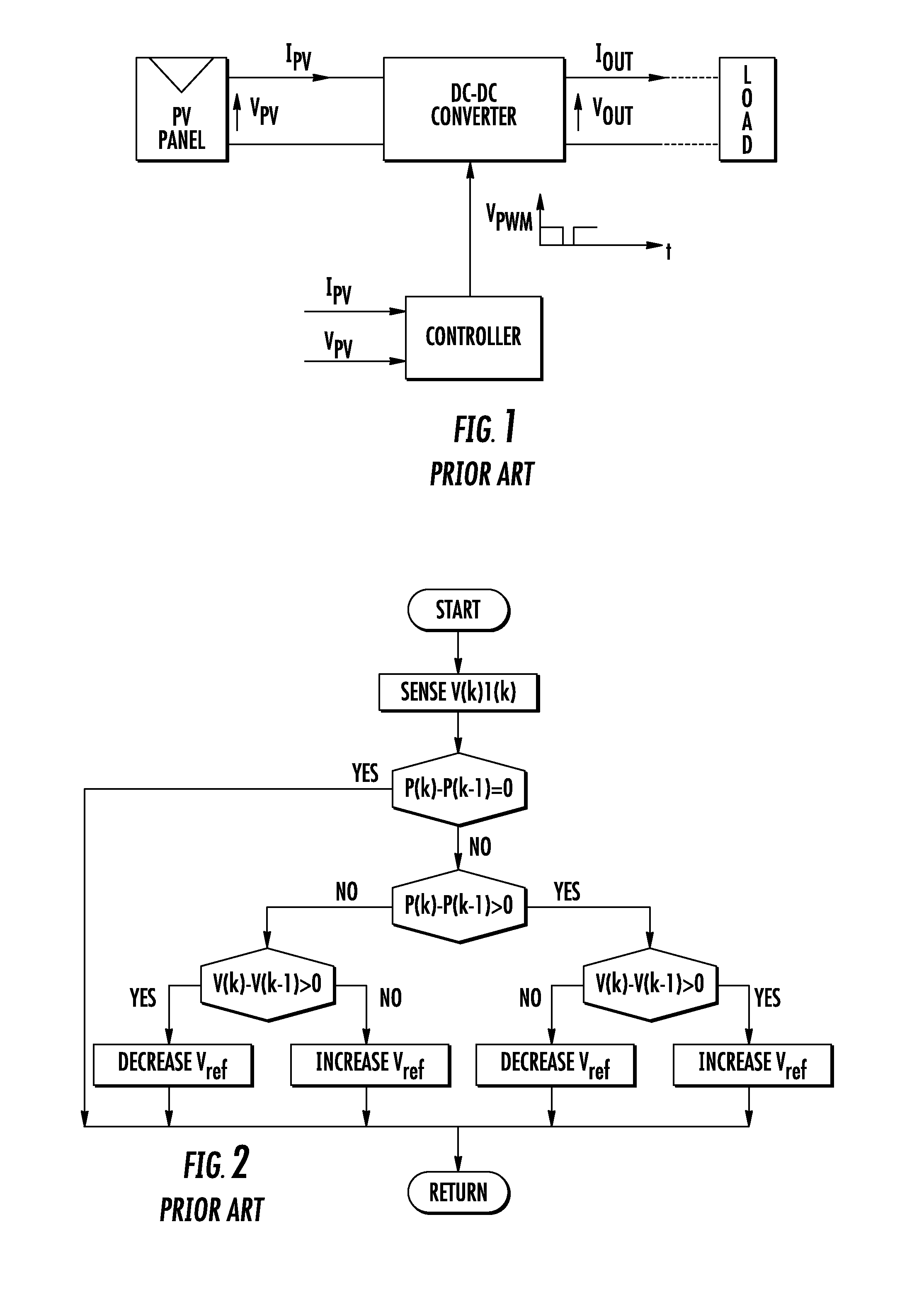
Moreover, only few methods are able to track the MPP using only one sensor [4], [7], [8].
Therefore, current monitoring may become difficult at low power rates, when the current drawn from PV panels is relatively small.
However, a current sensor is used, which suffers from the above noted drawback of needing a dissipative series resistance.

Method used


Image

  • Analog MPPT circuit for photovoltaic power plant
  • Analog MPPT circuit for photovoltaic power plant
  • Analog MPPT circuit for photovoltaic power plant

Examples


Embodiment Construction

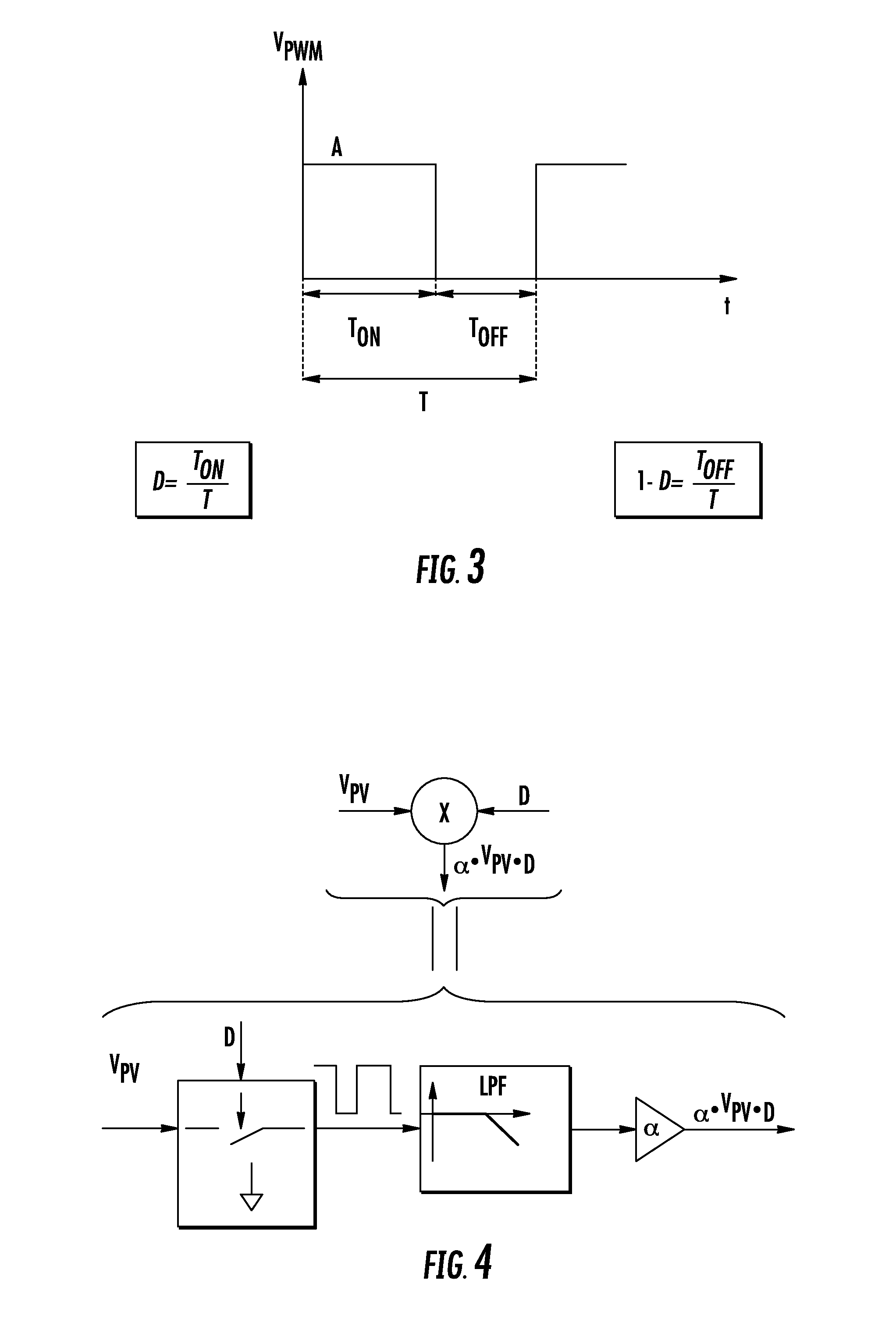
[0026]The duty cycle D of the power switch of a DC-DC converter is controlled by a Pulse Width Modulated (PWM) driving signal, VPWM. The ratio between the ON time and the whole period of the waveform is D, as shown in FIG. 3.

[0027]Monitoring of Power Extracted from the PV Panel

[0028]If the amplitude of the PWM driving signal is A and if it is applied to a low-pass filter, the resulting signal may be a constant voltage proportional to the product A*D as far as ripple can be neglected. Moreover the PWM signal may be used to switch the voltage between VPV and ground at the input of the same low-pass filter, such that the resulting output signal is a constant voltage proportional to VPV*D with negligible ripple. The product signal represents the power currently yielded from the PV panel or panels when the converter is functioning in discontinuous conduction mode (DCM).

[0029]A functional block diagram of hardware for performing such a multiplication is depicted in FIG. 4. FIG. 5 is an ex...


PUM


Abstract

A method of power point tracking for operating a photovoltaic power plant, which includes a DC-DC converter of the output voltage of a panel having a power switch driven by a PWM control signal of variable duty-cycle generated by a PWM control circuit, in discontinuous conduction mode or continuous conduction mode depending on the current load of the converter, is implemented by low cost analog circuits. The method does not require the use of any analog-to-digital conversion, digital processing or storage resources and may use a single voltage sensor.

Description

FIELD OF THE DISCLOSURE[0001]This disclosure relates to photovoltaic panel power plants and, in particular, to the techniques for maximum power point tracking (MPPT). The disclosed MPPT technique is effective in power plants wherein generated energy is stored in a battery array or is absorbed from the output of a DC-DC step-up converter at an output voltage relatively stable in the short term.BACKGROUND OF THE DISCLOSURE[0002]The cost of photovoltaic (PV) power plants is still high while energy conversion efficiency remains low. Besides the fact that the output power that solar panels can deliver varies with solar radiation, it also depends of how power is being transferred to the load. In other words, solar panels can deliver the maximum power only at specific working points of their V-I characteristics.[0003]Maximizing the power delivered by PV panels under changing load conditions may be desirable. During the last several decades, several methods have been proposed to track the m...

Claims


Application Information

Patent Timeline
Patent Type & Authority Patents(United States)
IPC IPC(8): G05F1/00
CPCH02J7/35Y02E10/566Y02E10/58Y02E10/56
Inventor RUA, FRANCESCOPRIVITERA, SALVATORE GIUSEPPESIGNORELLI, TIZIANA TERESAPULVIRENTI, FRANCESCO
Owner STMICROELECTRONICS SRL
Learn More