
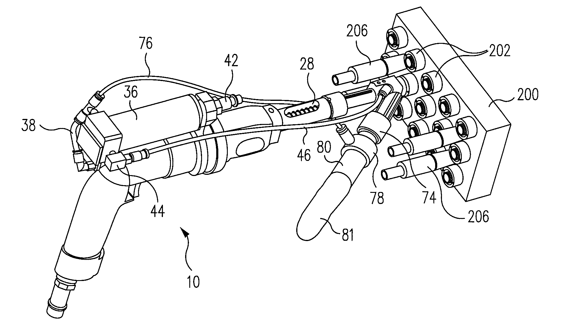
High speed hand drill with swiveling pressure foot and integrated vacuum pickup and coolant delivery duct

a high-speed, hand-held technology, applied in the field of power tools, can solve the problems of undesirable effects and foregoing disadvantages, and achieve the effect of improving the ergonomics of the tool and improving the drill guid

Active Publication Date: 2012-12-25
THE BOEING CO
View PDF27 Cites 14 Cited by
  • Summary
  • Abstract
  • Description
  • Claims
  • Application Information

AI Technical Summary

Benefits of technology

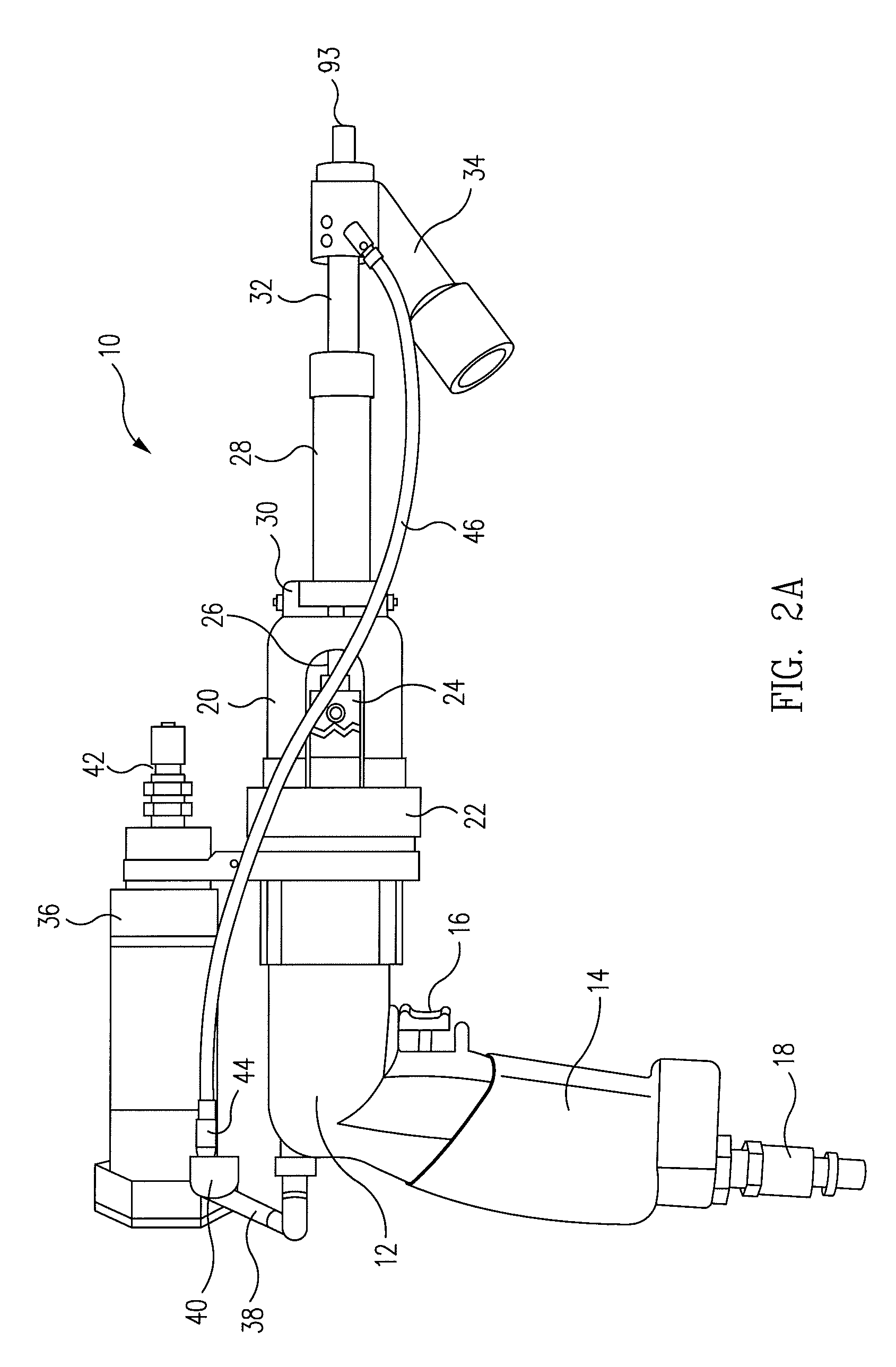
The patent describes a high-speed, handheld power drill that has a swiveling pressure foot and a vacuum pickup integrated with a coolant supply duct tool to pick up shavings and deliver coolant to the drill bit. The drill has improved ergonomics and is lighter than previous designs. It includes a drill guide and integrated nozzle chip collector and cutting lubricant supply duct. The drill may be used in manufacturing processes, such as aircraft assembly, to drill holes. The swiveling pressure foot allows for better access and placement of the drill, while the integrated lubricant / vacuum nozzle enables proper lubricant flow and vacuum for chip and coolant fluid vapor extraction. The ratcheting swivel design optimizes tool space usage, interchangeability, and ergonomics. The improved combination elbow fitting prevents damage to the conduit and improves ergonomics by maintaining a clear handle grip area. Overall, the drill has improved performance and efficiency in manufacturing processes.

Problems solved by technology

For example, shavings, dust, cuttings, cooling lubricant vapor, which may also be known as foreign object debris (FOD) from the drilling operation may become airborne and escape into the working environment, causing undesirable effects.
The foregoing disadvantages may be undesirable.

Method used


Image

  • High speed hand drill with swiveling pressure foot and integrated vacuum pickup and coolant delivery duct
  • High speed hand drill with swiveling pressure foot and integrated vacuum pickup and coolant delivery duct
  • High speed hand drill with swiveling pressure foot and integrated vacuum pickup and coolant delivery duct

Examples


Embodiment Construction

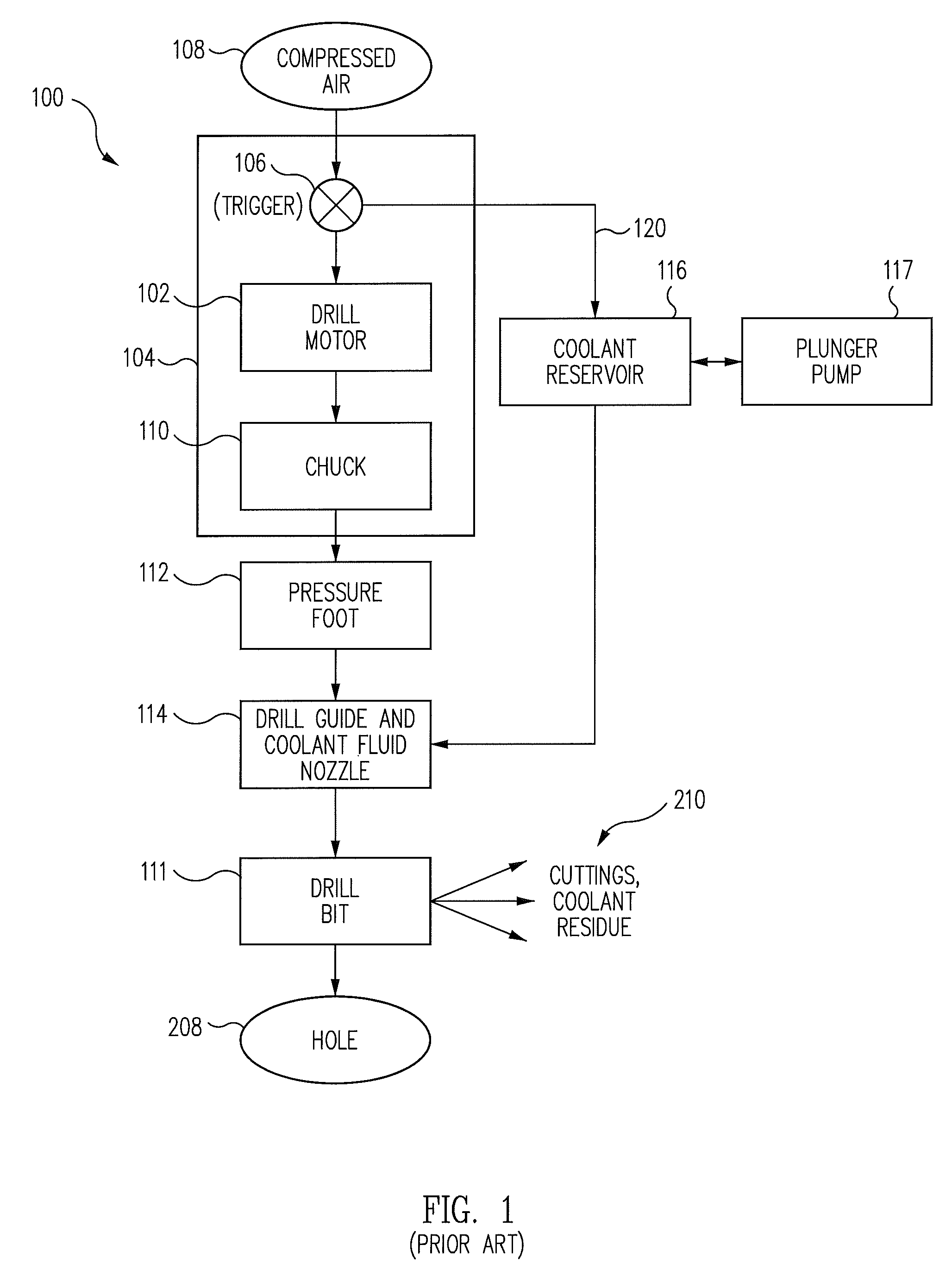
[0031]A high speed, handheld power drill 100 in accordance with the prior art is illustrated in the functional block diagram of FIG. 1. With reference to FIG. 1, the conventional power hand drill 100 may comprise a drill motor 102, which may be enclosed in a housing 104 and provided with a pistol grip handle (not shown), which may have a pull-trigger 106 for actuating the drill motor 102, which may be powered by compressed air supplied from a compressed air source 108.

[0032]A conventional chuck 110 for holding a drill bit 111 may also be disposed within the housing 104 and coupled to the motor 102 for rotation thereby. An elongated, fluted twist drill bit 111 may have an inner end clamped in the chuck 110 for rotation by the motor 102 and chuck 110 about a long axis thereof, and may include an opposite second, or cutting end (not shown) that extends forwardly from the housing 104. An elongated, annular “pressure foot”112 may be fixed at the front end of the housing 104 and may exten...


PUM

PropertyMeasurementUnit
angleaaaaaaaaaa
axial length Lfaaaaaaaaaa
length Lfaaaaaaaaaa

Abstract

A high speed handheld power drill includes a housing with a motor, a chuck rotationally driven by the motor, and a drill bit clamped in the chuck. A pressure foot is mounted on the housing for coaxial rotation about the drill bit and lockable in a selectable angular position relative to the housing. A drill guide is slidably disposed within the pressure foot at an outer end thereof and biased for coaxial sliding movement between the drill bit and pressure foot. A vacuum cuttings pickup and coolant fluid delivery tool is coupled to the drill guide and arranged to deliver coolant fluid to the drill bit and to remove drill cuttings and coolant fluid and vapor therefrom during drilling. A coolant fluid reservoir is coupled to the drill motor housing and adapted to deliver selectably metered amounts of coolant fluid to the cuttings pickup and coolant delivery tool during drilling.

Description

BACKGROUND[0001]The present disclosure relates to power tools, in general, and in particular, to a high speed, handheld power drill incorporating an integrated swiveling vacuum pickup and coolant duct.[0002]Handheld power tools may be used widely in a number of disparate manufacturing activities, including the aerospace, automotive, defense, shipbuilding, petroleum and construction industries, to name but a few. One of the more commonly used types of handheld power tools that finds widespread use may be handheld power drills, typically electrically or pneumatically powered. These drills may be used to drill holes into and through a wide variety of materials, including, without limitation, steel, aluminum, wood and composites, and for a wide variety of purposes.[0003]While powered hand drills may provide a relatively accurate and efficient mechanism for the rapid creation of holes and bores in work pieces, existing tools also have a number of draw-backs associated with them. For exam...

Claims


Application Information

Patent Timeline
Patent Type & Authority Patents(United States)
IPC IPC(8): B23B47/34B23B49/02B23B51/06
CPCB23B49/02B23Q11/0046B23Q11/10B23Q11/1092Y10T408/03Y10T408/44Y10T408/569Y10T408/50Y10T408/97Y10T408/56245
Inventor NGUYEN, PETER D.
Owner THE BOEING CO
Learn More