
Turbocharger protection device

a protection device and turbocharger technology, applied in the direction of machines/engines, instruments, heat measurement, etc., can solve the problems of turbocharger damage, deactivation, and high cost of electronic components for this purpose, and achieve the effect of reducing electronic costs and eliminating the risk of negative temperature characteristics

Inactive Publication Date: 2012-12-11
HERAEUS NEXENSOS GMBH
View PDF18 Cites 25 Cited by
  • Summary
  • Abstract
  • Description
  • Claims
  • Application Information

AI Technical Summary

Benefits of technology

[0004]It is the object of the present invention is to provide a reliable turbocharger protection device that requires lower electronic expense than thermocouples and that can also be used at temperatures between 900° C. and 1200° C., particularly at 1050° C. to 1150° C., and that also eliminates the risks of negative temperature characteristics.
[0005]To achieve the object the wear caused by vibrations in the turbocharger due to changes in temperature is reduced by particularly careful lightening of the temperature-dependent elongation work or partially prevented in an insulation. For this purpose, the supply line to the temperature-detection element, particularly a measurement resistor, is stabilized, on one hand, in that the supply line comprises a mineral-insulated supply line part, on whose end facing the temperature detection element, particularly the measurement resistor, strands project out from the insulation, on which the springs are placed that produce the connection between the strands and the temperature detection element, particularly the measurement resistor, or a connection wire located on the temperature detection element, particularly the measurement resistor. Alternatively, between the temperature detection element, particularly the measurement resistor, and a supply-line cable, a heat-decoupling wire is stretched on one side on the end facing the temperature detection element, particularly the measurement resistor, and is connected elastically on the other end to the supply-line cable. In both embodiments, the stresses on the conductor caused by changes in temperature and vibrations between the measurement resistor and the supply-line cable lead to no wear on the conductors, because the stresses are either cushioned or, in the case of mineral insulation, the strands are embedded tightly, so that they cannot generate elongation work and abrasion is excluded. The decisive feature is that the cushioning at high-temperature loads takes place without resonance vibrations perpendicular to the direction in which the elongation is cushioned and not within a high temperature-loaded insulation. Therefore, cushioning takes place according to the invention in the high-temperature range with a spring guided freely on an axis or displacement of the spring outside of the temperature load.
[0007]According to the invention, simple temperature sensors are also provided, particularly high-temperature sensors, in which a heat-decoupling wire is arranged between the temperature detection element, particularly the measurement resistor, of the chip and the supply-line cable, wherein, according to the invention, the heat-decoupling wire is stretched on one side at the end facing the temperature detection element, particularly the measurement resistor, and is connected elastically to the supply-line cable at the other end.
[0009]According to the invention, both embodiments relieve stress on the thin heat-resistant connection wires, particularly bonding wires, on the temperature detection element, particularly chip or NTC thermistor, which typically supply the thermosensitive unit with power via pads (contact fields).
[0010]These temperature sensors exhibit excellent stability with changes in temperature, particularly with respect to rapid changes in temperature, are suitable as high-temperature sensors, and allow turbocharger overheating protection devices to be operated reliably with simple electronics.

Problems solved by technology

The electronics for this purpose are expensive.
One problem with negative temperature characteristics is that, if there is drift, the deactivation takes place at temperatures that are too high and the turbocharger suffers damage.

Method used


Image

  • Turbocharger protection device
  • Turbocharger protection device
  • Turbocharger protection device

Examples


example 1

[0028]Temperature sensor whose measurement tip can be adapted, particularly bent, according to the requirements of motor construction.

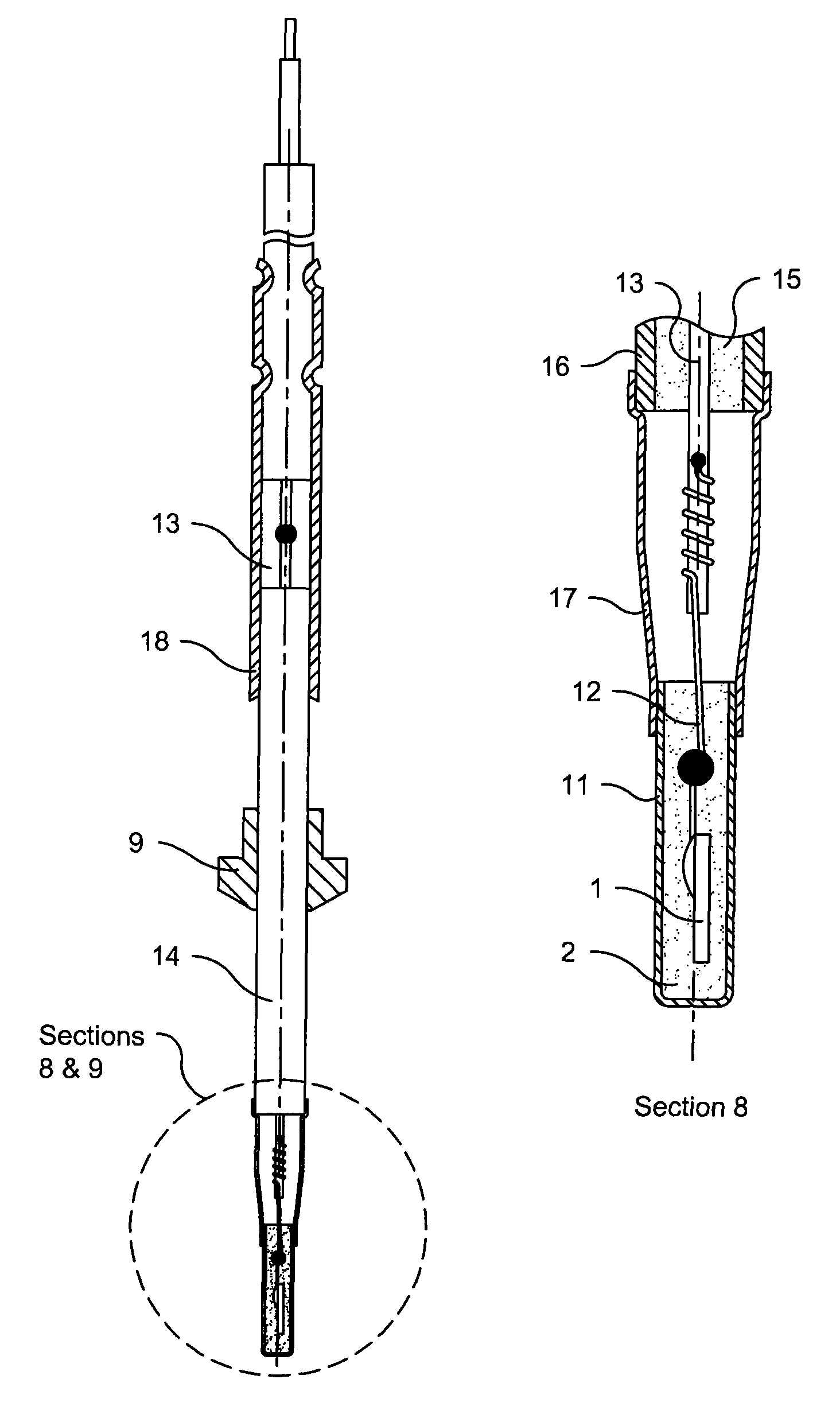
[0029]A high temperature sensor with flexible measurement tip has a bendable MI line according to FIG. 6 or 7, on which a measurement tip is arranged, which can be constructed according to FIG. 8 or 9. The film resistor 1 shown in FIG. 8 is connected with two bonding wires (only one shown in Figures) each to a spiral spring, which are each in turn mounted on a strand of an MI line and surround this line.

[0030]In this way, the connection between the measurement resistor chip and the supply-line cable is produced at least partially such that, between the measurement resistor and the supply-line cable, strands from a mineral-insulated supply line project out from the mineral insulation at the end facing the measurement resistor and are each connected electrically and mechanically to a spring, and the springs are each guided wound around the strands.

[0031...

example 2

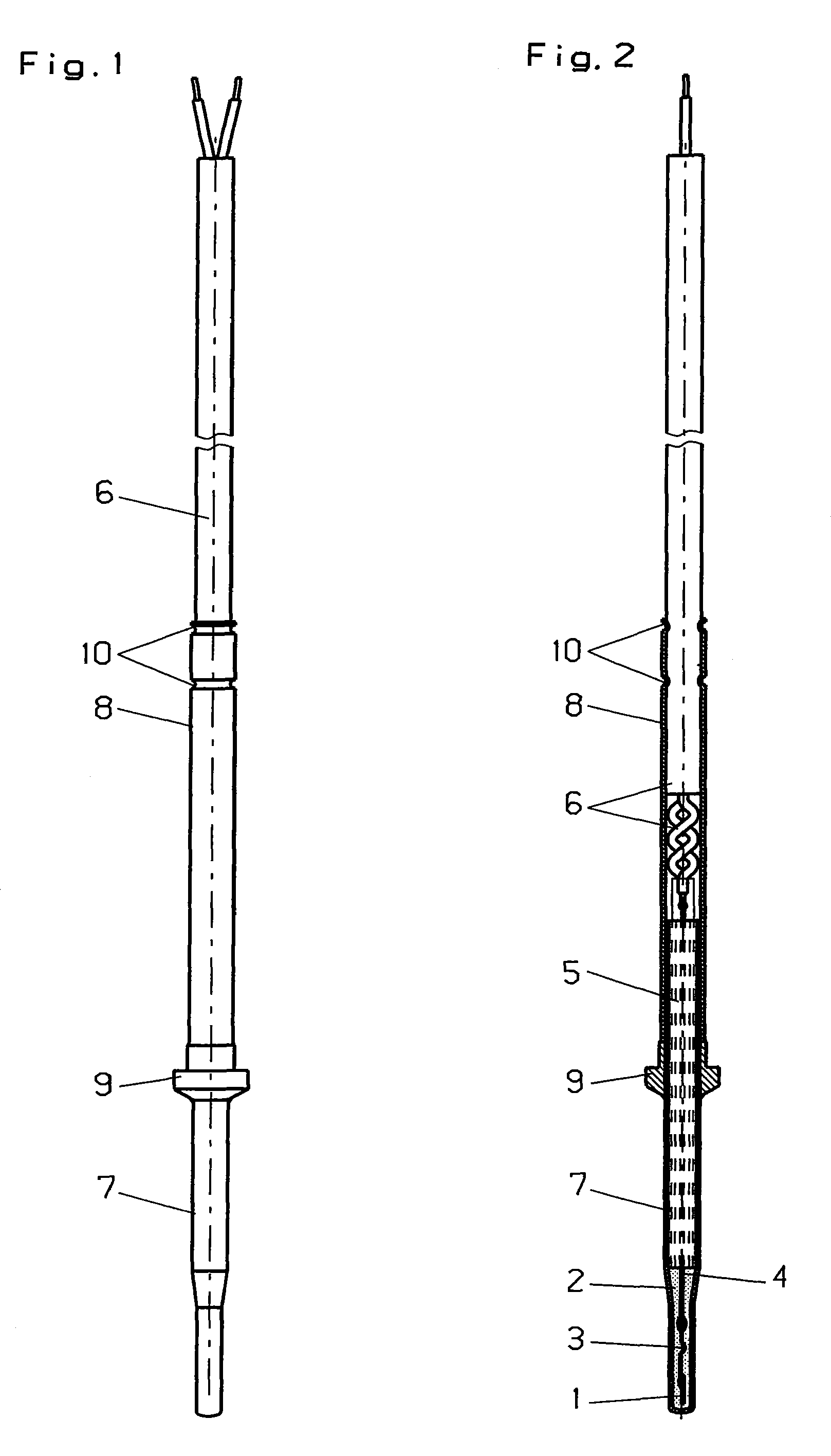
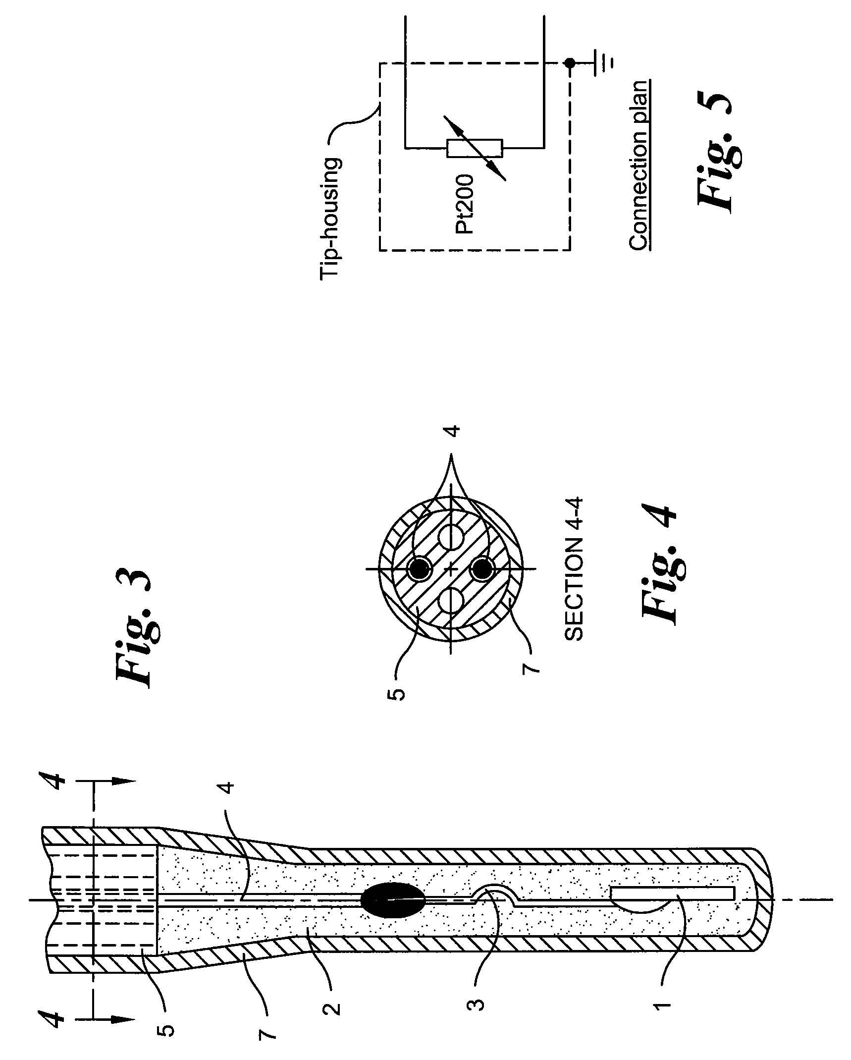
[0037]With a chip 1 made of a platinum thin-film measurement resistor on a sapphire substrate, a high-temperature sensor element is created for a temperature range from −40° C. to 1200° C. The chip 1 is embedded in a casting compound 2 made of highly pure aluminum oxide and connected electrically with spring-shaped bonding wires 3 made of platinum to heat-decoupling wires 4 made of chromium steel having 70 wt. % iron, 25 wt. % chromium, and 5 wt. % aluminum (FIG. 4). The heat-decoupling wires 4 according to the invention are surrounded essentially by a capillary tube 5 made of aluminum oxide (FIG. 3). On its end opposite the chip 1, the heat-decoupling wires 4 are connected to spiral-shaped strands of the connection cable 6 (FIGS. 1 and 2).

[0038]The casting compound 2 is dosed and fired in a sleeve 7 made of chromium steel having 70 wt. % iron, 25 wt. % chromium, and 5 wt. % aluminum. The casting compound mass is thereby sintered and fixes the chip 1. This embodiment is suitable esp...


PUM

PropertyMeasurementUnit
temperatureaaaaaaaaaa

Abstract

A temperature sensor, particularly a high-temperature sensor, is provided in which an MI line or a heat-decoupling wire is arranged between the measurement resistor (chip) and the supply-line cable. Springs are stuck on the strands of the MI line, whereby the contacting to the measurement resistor is realized, or the heat-decoupling wire is stretched on one side to the end facing the measurement resistor and is connected elastically on the other end to the supply-line cable.

Description

CROSS-REFERENCE TO RELATED APPLICATIONS[0001]This application is a Section 371 of International Application No. PCT / EP2008 / 000717, filed Jan. 30, 2008, which was published in the German language on Sep. 4, 2008, under International Publication No. WO 2008 / 104259 A2 and the disclosure of which is incorporated herein by reference.BACKGROUND OF THE INVENTION[0002]The invention relates to a turbocharger protection device, to temperature sensors suitable as components for this device, and to methods for their production. Turbochargers must be protected from overheating, which is why they are equipped with an appropriate protection device. For this purpose, switch-off devices are used for diesel turbochargers at 900° C. to 1050° C. and for gasoline engines up to 1120° C.[0003]For gasoline engines, only thermocouples that took advantage of the Seebeck effect were previously used for this purpose. The electronics for this purpose are expensive. Up to 900° C. semiconductor temperature elemen...

Claims


Application Information

Patent Timeline
Patent Type & Authority Patents(United States)
IPC IPC(8): G01K1/12G01K7/22
CPCG01K1/12G01K7/16Y10T29/49124G01K2205/02F02B39/16
Inventor WIENAND, KARLHEINZBACHMANN, MARIOMUZIOL, MATTHIASLOOSE, THOMAS
Owner HERAEUS NEXENSOS GMBH
Learn More