Advertisement display system
a display system and display technology, applied in the field of advertisement display systems, can solve the problems of danger to the safety of drivers or pedestrians, difficulty in connecting electric cables or attaching sensors to traffic signals or alarms at railway crossings, and difficulty in analyzing advertisements, etc., to achieve high advertisement effectiveness, high accuracy and precise control of advertisement display
- Summary
- Abstract
- Description
- Claims
- Application Information
AI Technical Summary
Benefits of technology
Problems solved by technology
Method used
Image
Examples
first embodiment
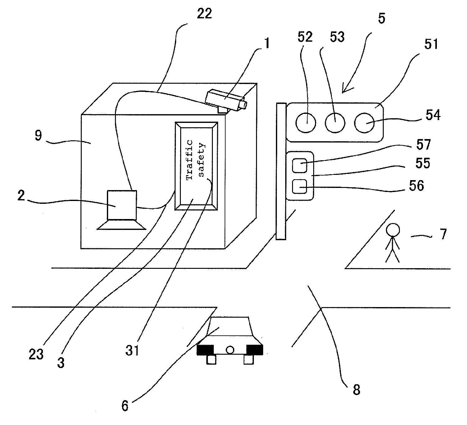
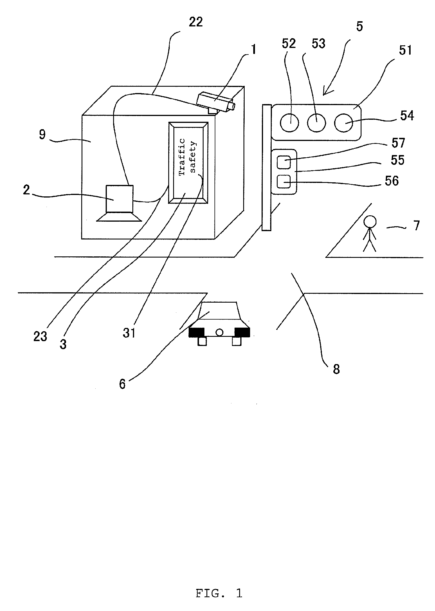
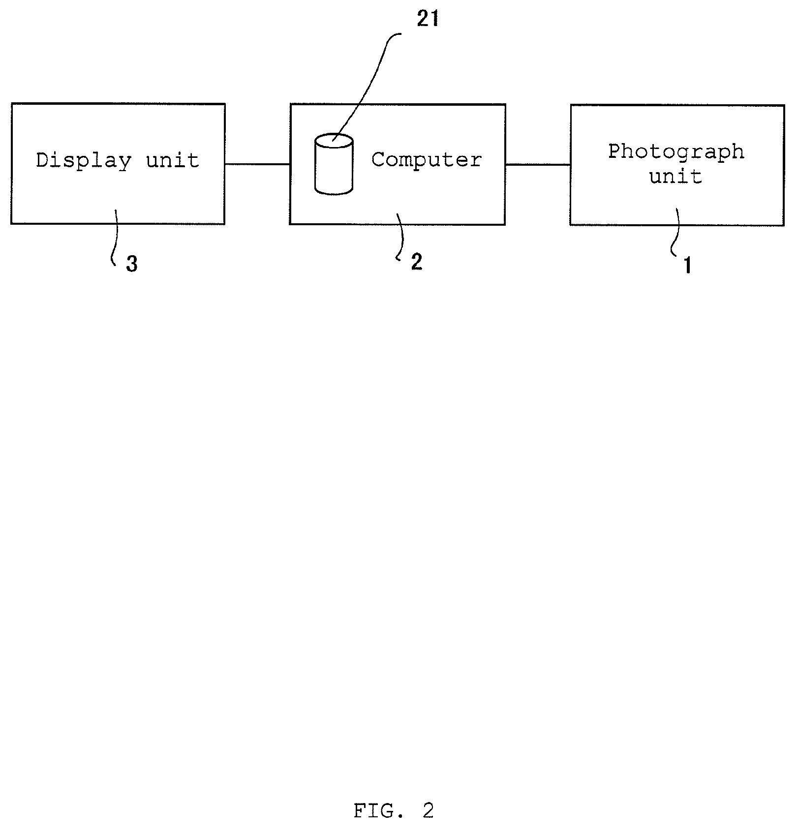
[0089]The advertisement display system of the present invention has a following configuration: An advertisement display information to be displayed on the display unit 3 is stored in the computer 2 and an image data taken by the photograph unit 1 is analyzed by the computer 2; a display body data as the advertisement display information is extracted from a database 21 on the basis of the analyzed signal condition; and the display body data is output to the display unit 3 to control advertisement display by the display unit.
[0090]The photograph unit 1 is a digital camera or a video camera for taking an image which can take a photograph of the signal condition of the traffic signal 5 with a certain time interval and is provided at a location from which the signal condition of the traffic signal 5 in the vicinity of an intersection 8 can be taken, for example, top of a building 9 or an external wall thereof.
[0091]The photograph unit 1 includes various parts such as a body, a lens, and ...
second embodiment
[0117]Here, in the second embodiment described above, an example of a simple configuration where a database 41 is provided in the display unit 4 is shown. However, in a case where the display unit 4 is an electric display, matrix information for controlling the LED to be lit may be stored as a database and in a case where the display unit 4 is an image display monitor, the advertisement display information content may be stored as a database. In this case also, the advertisement information content is switched by the display body switching signal from the computer 2.
[0118]A usage condition of the advertisement display system of the first embodiment will be shown based on FIG. 8. The photograph unit 1 takes photographs of the signal condition of the traffic signal 5 with a certain interval, preferably time interval of one second or less, and transmits the image data to the computer 2 (S1).
[0119]The computer 2 analyzes change in the signal condition from the image data transmitted fro...
third embodiment
[0130]In the advertisement display system of the present invention, the optical sensor 102 is attached to the screen 106 of the image display unit 101, at least part of the image displayed on the screen 106 is detected by the optical sensor 102, and an advertisement display information stored in the display unit 4 is displayed on the display unit 4 by the relay unit 103.
[0131]In the advertisement display system of the present embodiment, optical sensors 102 are attached to spots which correspond to display positions of each signal light displayed on the screen 106 and if the optical sensor part 107 of the optical sensor 102 detects lighting of the signal light displayed on the screen 106, a signal is output to the display unit 4 so that the display body to be displayed on the display unit 4 is switched. That is, for a traffic signal for a vehicle, a total of three optical sensors 102 are attached to positions corresponding to green light, yellow light, and red light and the optical ...
PUM
 Abstract
Description
Claims
Application Information
 - R&D
- Intellectual Property
- Life Sciences
- Materials
- Tech Scout
- Unparalleled Data Quality
- Higher Quality Content
- 60% Fewer Hallucinations
Browse by: Latest US Patents, China's latest patents, Technical Efficacy Thesaurus, Application Domain, Technology Topic, Popular Technical Reports.
© 2025 PatSnap. All rights reserved.Legal|Privacy policy|Modern Slavery Act Transparency Statement|Sitemap|About US| Contact US: help@patsnap.com


