Apparatus for treating a portion of a reproductive system and related methods of use
a technology for a reproductive system and an apparatus, applied in the field of uterine amputation devices and methods, can solve the problems of limited visibility, limited laparoscopic surgery in general, and difficulty in manipulating internal organs with laparoscopic tools
- Summary
- Abstract
- Description
- Claims
- Application Information
AI Technical Summary
Benefits of technology
Problems solved by technology
Method used
Image
Examples
first embodiment
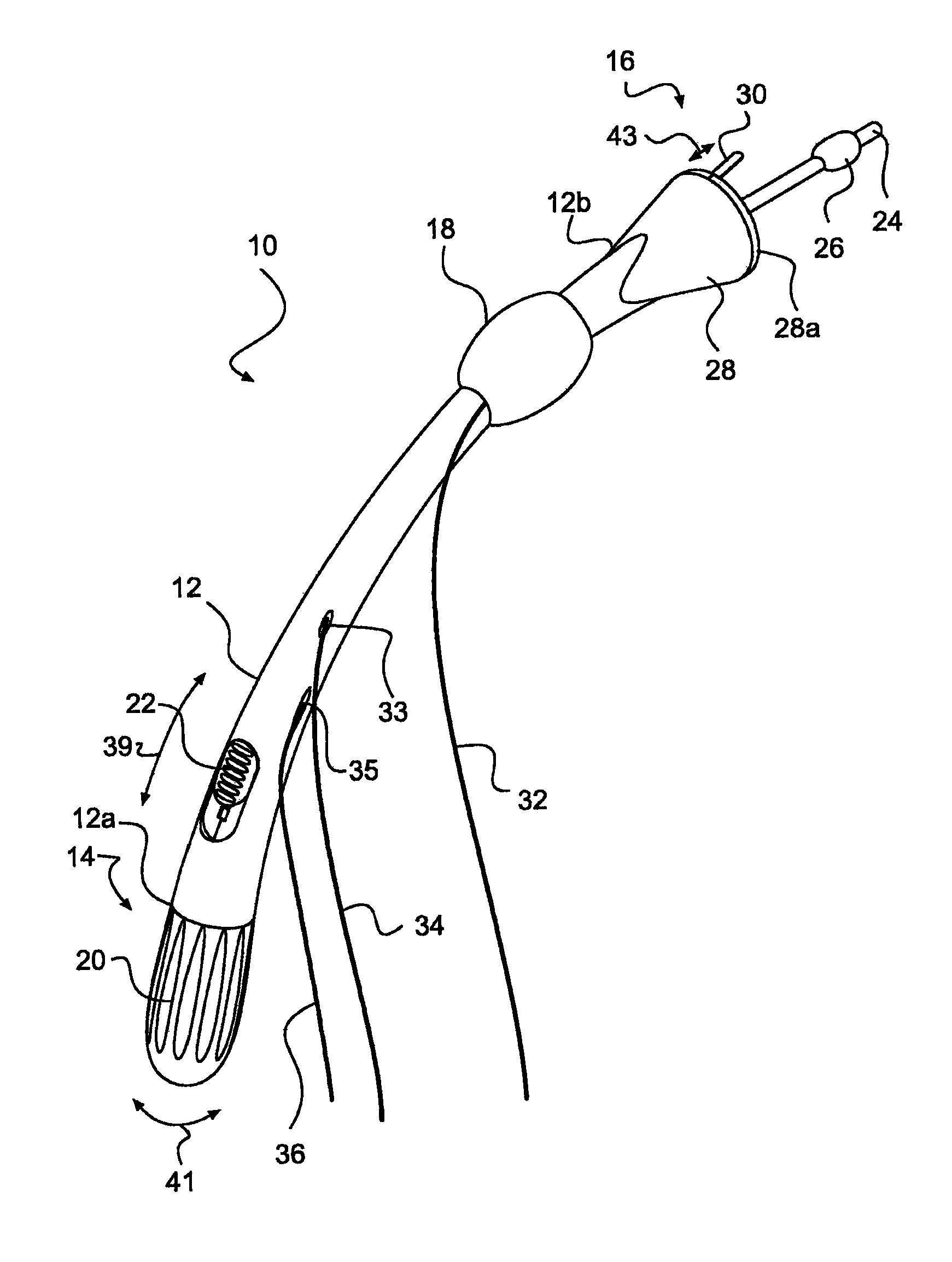
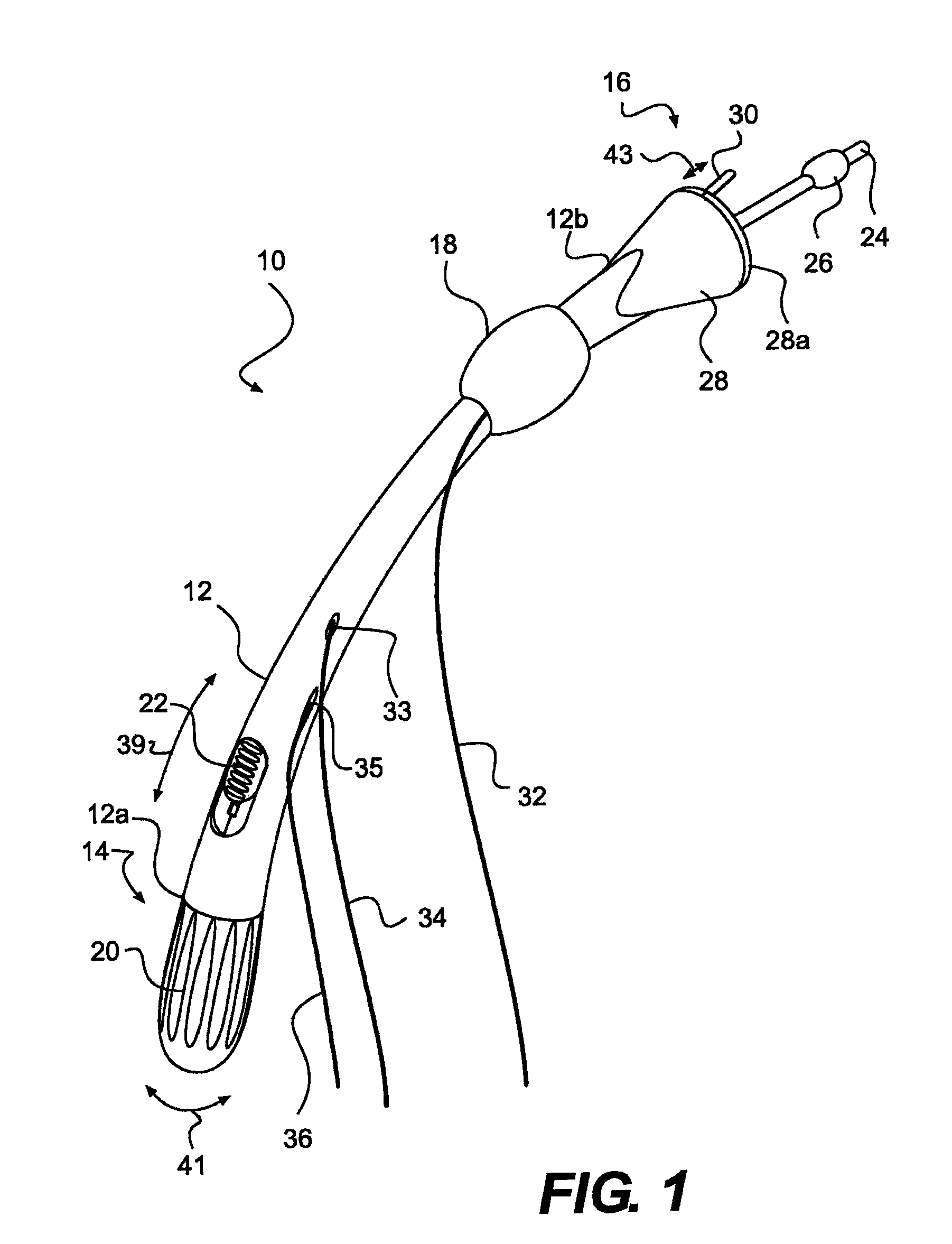
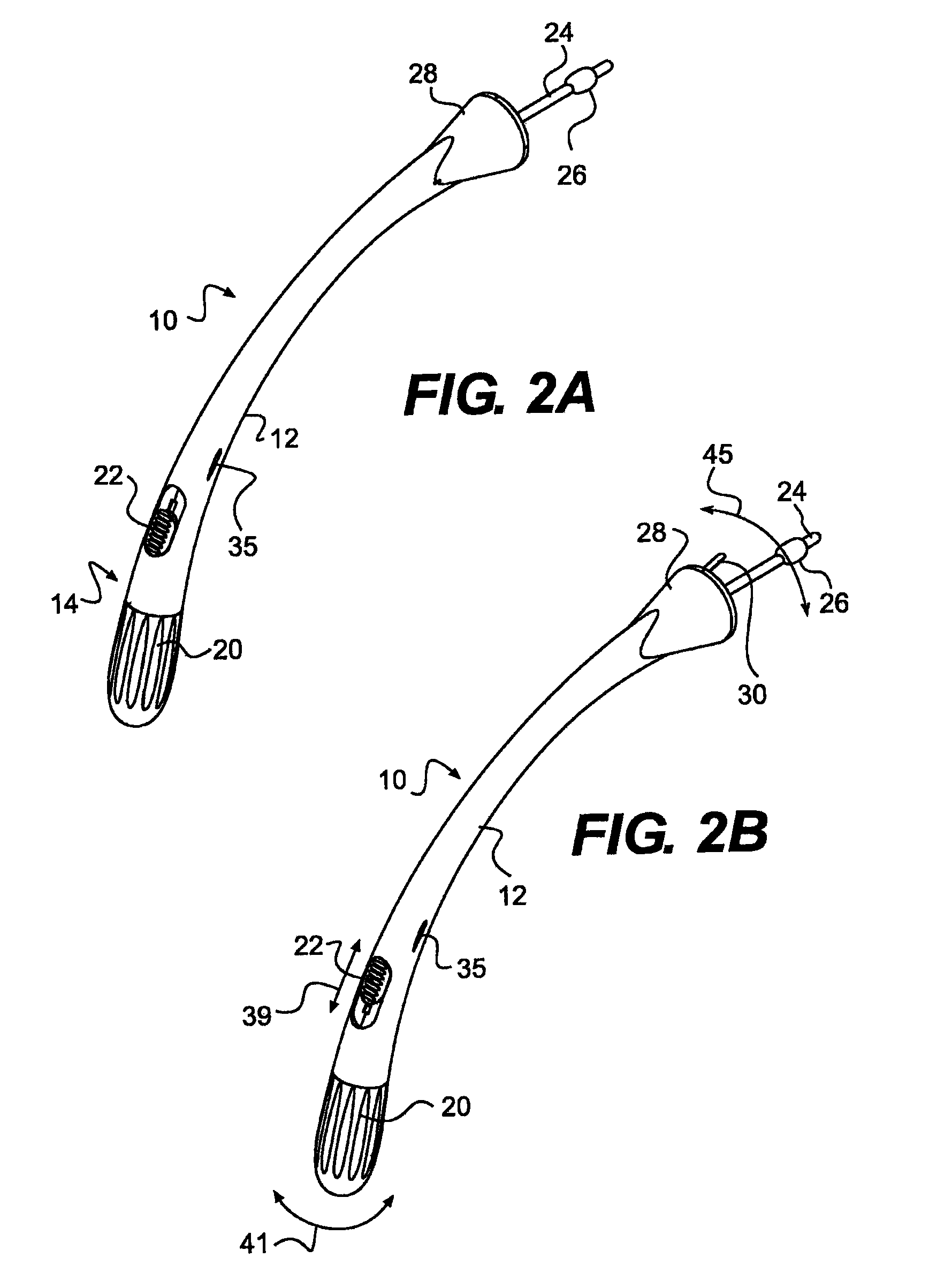
[0063]FIG. 1 illustrates a medical device 10 for performing a TLH procedure, in accordance with the present disclosure. Medical device 10 may include an elongate member 12, an end effector assembly 16, and a handle portion 14. For purposes of this disclosure, “proximal” refers to the end closer to the device operator during use, and “distal” refers to the end further from the device operator during use. End effector assembly 16 may be disposed at a distal end portion 12b of elongate member 12, and handle portion 14 may be disposed at a proximal end portion 12a of elongate member 12.
[0064]Elongate member 12 may be a unitary hollow structure, including, but not limited to, a curved tube made from any known suitable biocompatible material having sufficient flexibility and / or rigidity to traverse a vaginal canal. Alternatively, elongate member 12 may include two halves 13, 15 (FIG. 3) that may be connected by welding, soldering, or any other connection means known to those skilled in th...
fourth embodiment
[0100]FIG. 15 illustrates another medical device 1000 for performing a TLH procedure, in accordance with the present disclosure. Medical device 1000 may include one or more of the features of any of the other embodiments disclosed herein. For example, medical device 1000 may include a first elongate member 1020 and a second elongate member (collectively referred to as “1020a-b”) disposed therein. The second elongate member 1020a-b may include two halves 1020a, 1020b. First and second elongate members 1020, 1020a-b may be hollow, tubular structures and may have any cross-sectional shape and desired dimension, so long as they may be received in a vaginal canal. First elongate member 1020 may be a unitary structure. The second elongate member 1020a-b may also be a unitary structure. Alternatively, as noted above, the second elongate member 1020a-b may include two halves 1020a, 1020b, as shown in FIG. 16. Halves 1020a, 1020b may be connected via welding, soldering, or any other connecti...
fifth embodiment
[0106]FIG. 18 illustrates a medical device 400 for a laparoscopic supracervical hysterectomy (LSH) procedure, in accordance with the present disclosure. Medical device 400 may include one or more of the features of medical device 100 illustrated in FIG. 10. For example, medical device 400 may include an elongate member 120 and a handle portion 140. Medical device 400 may also include an end effector assembly 460. End effector assembly 460 may be capable of pivoting between a first position 243 and a second position 245 in the directions of arrow 241 in response to pivotal motion of handle portion 140 between its first pivotal position 199 and second pivotal position 201 in the directions of arrow 203.
[0107]End effector assembly 460 may include a manipulation device 440 with a cutting device 430 located therein. Cutting device 430 may include one or more of the features of cutting device 130 described in FIG. 10. Cutting device 430 may be any cutting device known to those skilled in ...
PUM
 Abstract
Description
Claims
Application Information
 - R&D
- Intellectual Property
- Life Sciences
- Materials
- Tech Scout
- Unparalleled Data Quality
- Higher Quality Content
- 60% Fewer Hallucinations
Browse by: Latest US Patents, China's latest patents, Technical Efficacy Thesaurus, Application Domain, Technology Topic, Popular Technical Reports.
© 2025 PatSnap. All rights reserved.Legal|Privacy policy|Modern Slavery Act Transparency Statement|Sitemap|About US| Contact US: help@patsnap.com


