
File server device arranged in a local area network and being communicable with an external server arranged in a wide area network

a file server and wide area network technology, applied in the field of local area networks, can solve the problems of increasing communication load, reducing server load, and complicated relay communication sessions established between relay servers, and achieve the effect of reducing server load

Active Publication Date: 2012-11-20
MURATA MASCH LTD
View PDF126 Cites 18 Cited by
  • Summary
  • Abstract
  • Description
  • Claims
  • Application Information

AI Technical Summary

Benefits of technology

The system reduces communication load between relay servers and allows for dynamic response to terminal movements, maintaining efficient communication across LANs by automatically updating and sharing account information and relay paths, thus enhancing network flexibility and responsiveness.

Problems solved by technology

However, in this case as well, each relay server must establish a relay communication session that is directly communicable with another relay server to relay the communication data, thereby complicating the relay communication session established between the relay servers, and increasing the communication load.
Furthermore, when the registered account information changes due to movement of the communication terminal and the like, the communication session between the relay servers that is already established becomes unnecessary, and a new relay session must be established at the destination, in which case, management becomes difficult and troublesome, and furthermore, response cannot be achieved in real time.

Method used


Image

  • File server device arranged in a local area network and being communicable with an external server arranged in a wide area network
  • File server device arranged in a local area network and being communicable with an external server arranged in a wide area network
  • File server device arranged in a local area network and being communicable with an external server arranged in a wide area network

Examples


first preferred embodiment

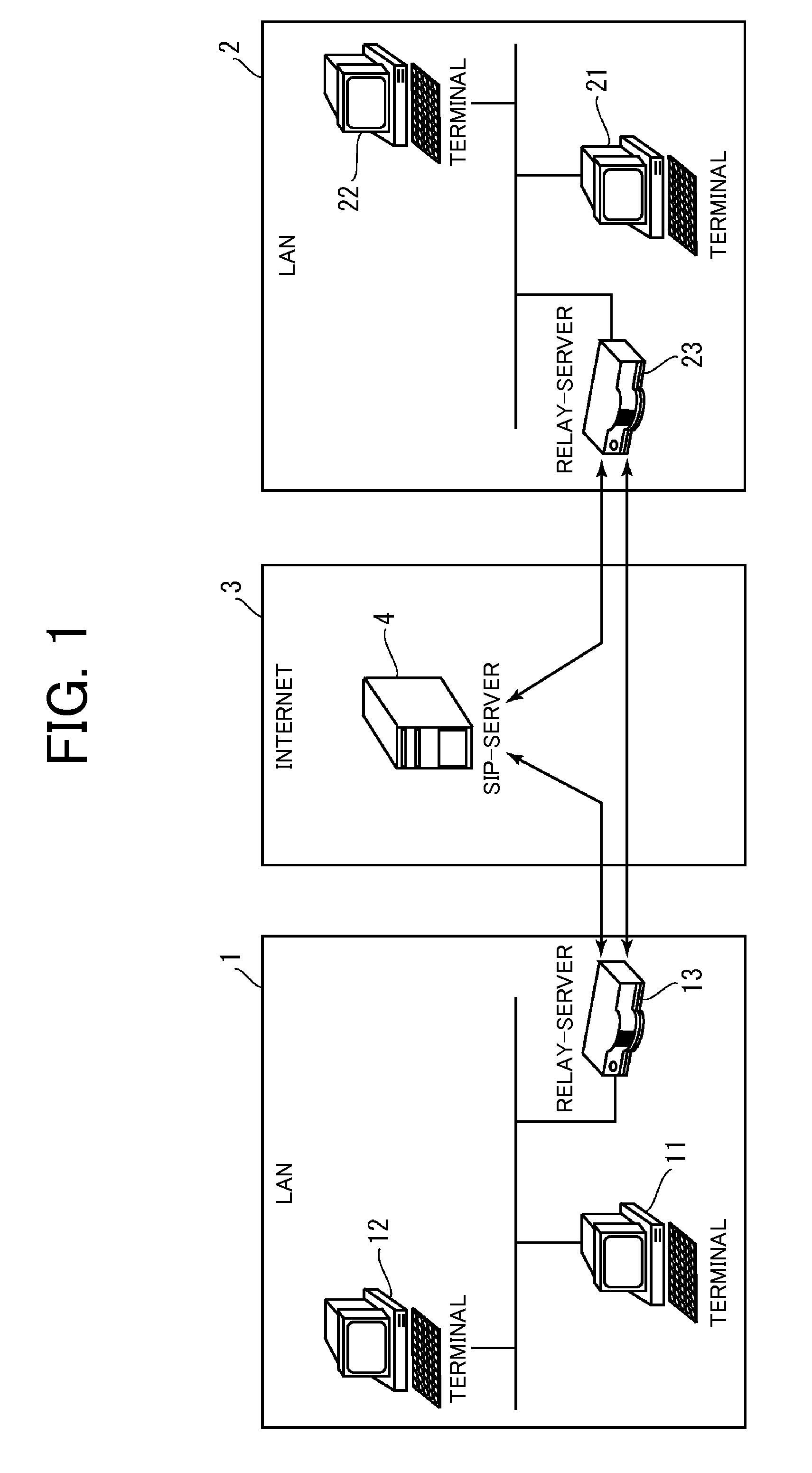
[0056]A first preferred embodiment of the present invention will now be described with reference to the drawings. FIG. 1 is an overall view of a communication system according to the present preferred embodiment. The communication system preferably includes an Internet 3, and two LANs 1 and 2 connected to the Internet 3. The LANs 1, 2 are networks at physically remote locations. For example, the LAN 1 is a local network in a central office building, whereas the LAN 2 is a local network in another branch office building, where the two LANs 1 and 2 are respectively connected to the Internet 3, which is a global network.

[0057]As illustrated in the figure, communication terminals 11, 12 are connected to the LAN 1. The communication terminals 11, 12 are respectively given a private IP address. Generally, a private IP address managed uniquely only in the LAN is given to the terminal connected to the LAN. The LAN 1 is connected with a relay server 13. The relay server 13 is connected to th...

second preferred embodiment

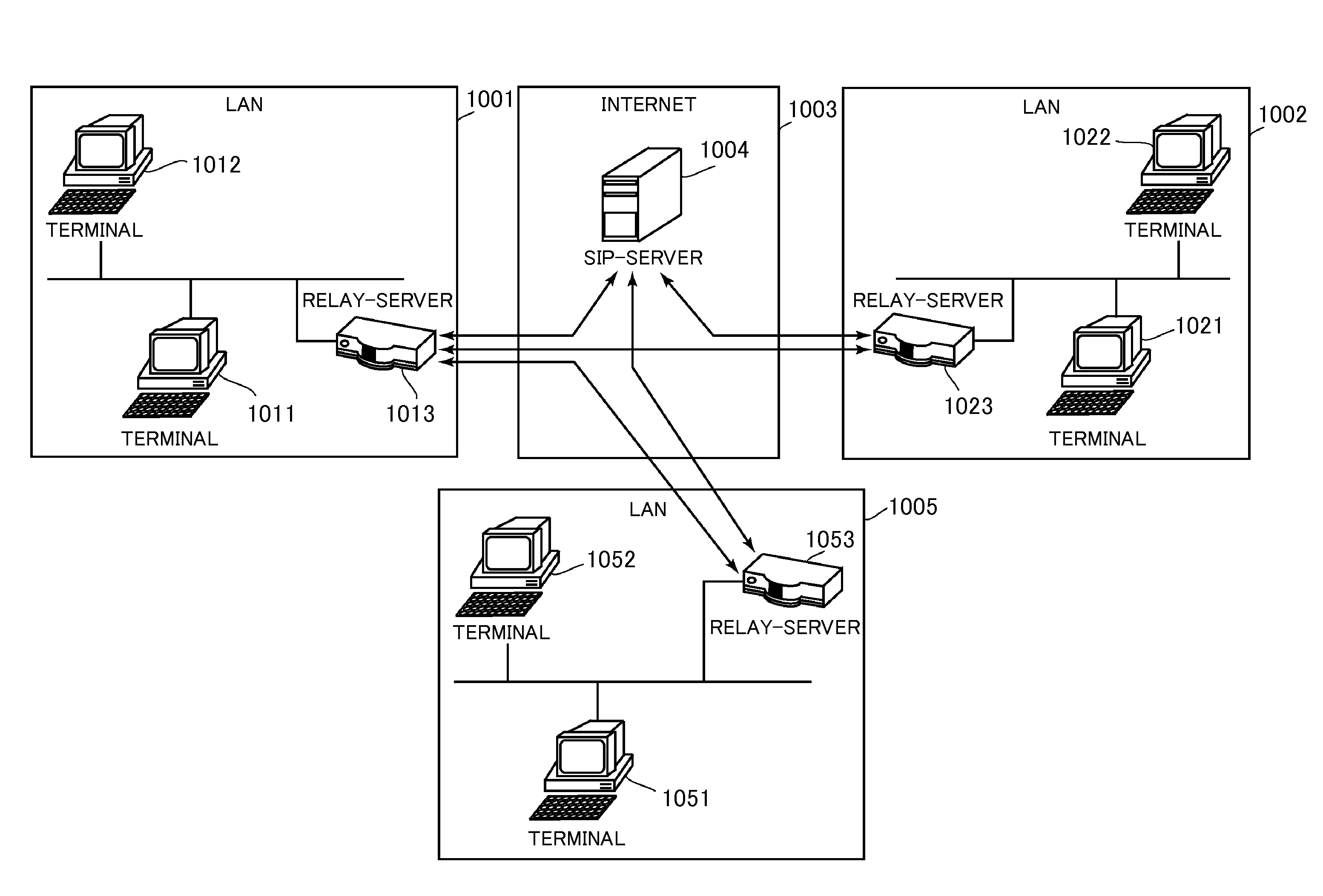
[0113]A second preferred embodiment of the present invention will now be described with reference to the drawings. FIG. 7 is an overall view of a communication system according to the present preferred embodiment. The communication system preferably includes an Internet 1003, and three LANs 1001, 1002, and 1005 connected to an Internet 1003. The LANs 1001, 1002, and 1005 are networks at physically remote locations. For example, the LAN 1001 is a local network in a central office building, whereas the LANs 1002 and 1005 are local networks respectively provided in other branch office buildings, where the three LAN 1001, 1002, and 1005 are respectively connected to the Internet 1003, which is a global network.

[0114]As illustrated in the figure, communication terminals 1011, 1012 are connected to the LAN 1001. The communication terminals 1011, 1012 are respectively given a private IP address. Generally, a private IP address managed uniquely only in the LAN is given to the terminal conne...

third preferred embodiment

[0192]A third preferred embodiment of the present invention will now be described with reference to the drawings. FIG. 13 is an overall view of a communication system according to the present preferred embodiment. The communication system preferably includes an Internet 2003, and three LANs 2001, 2002, and 2005 connected to the Internet 2003. The LANs 2001, 2002, and 2005 are networks at physically remote locations. For example, the LAN 2001 is a local network in the central office building, whereas the LANs 2002 and 2005 are local networks respectively provided in other branch office buildings, where the three LANs 2001, 2002, and 2005 are respectively connected to the Internet 2003, which is a global network.

[0193]As illustrated in FIG. 13, communication terminals 2011, 2012, 2021, 2022, 2051, and 2052 are connected to the respective LAN 2001, 2002, and 2005. A private IP address managed uniquely only in the respective LAN is given to each communication terminal. An account associ...


PUM


Abstract

Communication is established between communication terminals arranged in different LANS while realizing dynamic response to reduction in server load, movement of communication terminal, and the like. A relay server is arranged in a LAN and can communicate with an SIP server arranged in a WAN. For instance, a first relay server exchanges account information of the communication terminals in the respective LAN with a second relay server. If exchanged account information is changed in one relay server, the account information after the change is notified to the other relay server. One relay server determines the other relay server based on the exchanged account information and relays communication data between the communication terminals through the other relay server.

Description

CROSS-REFERENCE TO RELATED APPLICATIONS[0001]This application claims priority under 35 U.S.C. 119 to Japanese Patent Application No. 2006-277183, filed on Oct. 11, 2006, No. 2006-277811, filed on Oct. 11, 2006 and No. 2006-277996, filed on Oct. 11, 2006, which applications are hereby incorporated by reference in their entirety.BACKGROUND OF THE INVENTION[0002]1. Field of the Invention[0003]The present invention relates to a technique in which communication terminals in a plurality of different LANs (Local Area Networks) communicate over a WAN (Wide Area Network), in particular, to a communication technique between relay servers for relaying the communication.[0004]2. Description of the Related Art[0005]The communication terminals in the different LANs can directly communicate with each other over a WAN using a call control protocol such as SIP (Session Initiation Protocol) and DDNS (Dynamic Domain Name System). This is a technique referred to as a so-called VPN (Virtual Private Netw...

Claims


Application Information

Patent Timeline
Patent Type & Authority Patents(United States)
IPC IPC(8): G06F15/16
CPCH04L67/141H04L67/14H04L67/148H04L65/1045H04L65/1104H04L67/563H04L67/63H04L65/1073
Inventor TANIMOTO, YOSHIFUMI
Owner MURATA MASCH LTD
Learn More