Liquid ejecting head
a technology of liquid ejector and ejector shaft, which is applied in printing and other directions, can solve the problems of connection failure and difficulty in ensuring reliability in connection with flexible cable terminals, and achieve the effect of high reliability
- Summary
- Abstract
- Description
- Claims
- Application Information
AI Technical Summary
Benefits of technology
Problems solved by technology
Method used
Image
Examples
first embodiment
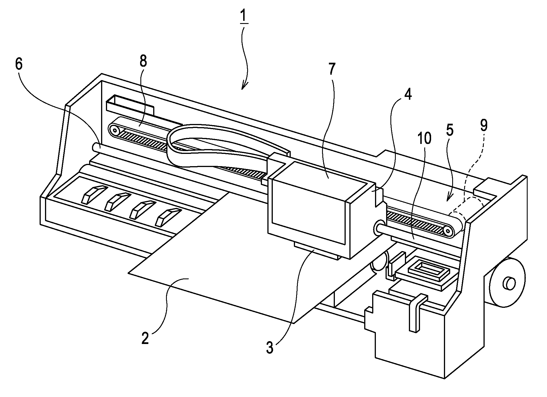
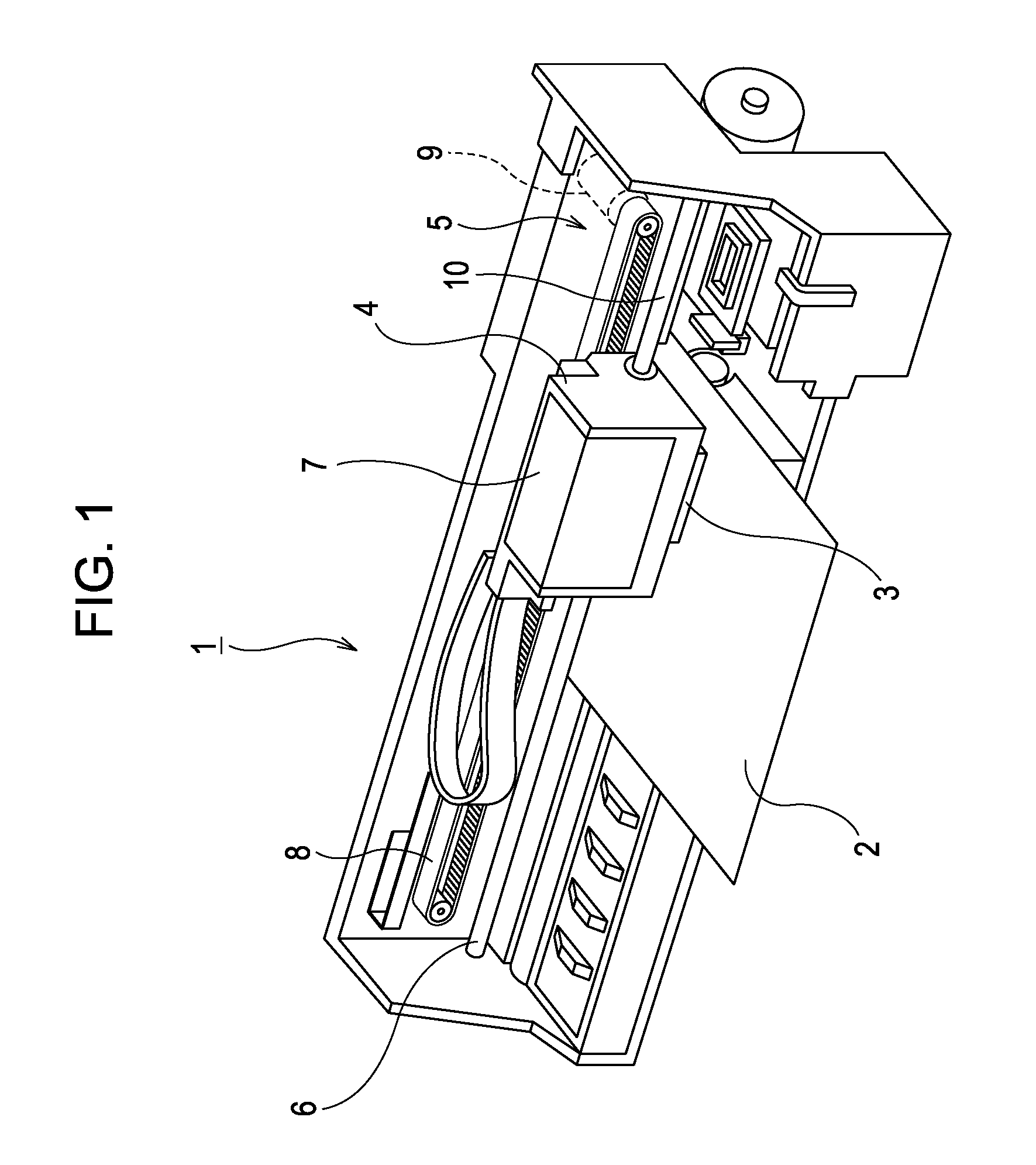
[0028]First, a general configuration of a printer is explained with reference to FIG. 1. A printer 1 is an apparatus that performs recording of images and the like by ejecting ink in a liquid form to a surface of a recording medium 2 such as a recording sheet. The printer 1 includes a recording head 3 that ejects ink, a carriage 4 on which the recording head 3 is mounted, a carriage movement mechanism 5 that moves the carriage 4 in a primary scanning direction, a platen roller 6 that moves the recording medium 2 in a secondary scanning direction. Here, the above-mentioned ink is a type of liquid of the invention, which is stored in an ink cartridge 7. The ink cartridge 7 is removably attached to the recording head 3. A configuration may also be employed in which the ink cartridge 7 is disposed on the body of the printer 1 such that ink is supplied from the ink cartridge 7 to the recording head 3 via an ink supply tube.
[0029]The carriage movement mechanism 5 includes a timing belt 8...
second embodiment
[0045]Further, the individual element electrode terminals 48 (a type of individual electrode terminal) each having a strip shape in plan view and electrically connected to the corresponding individual element electrodes 47 are disposed in a plurality of rows lying in the direction of the row of the pressure chambers 31 (the nozzle row direction) between the adjacent nozzle rows. More specifically, the individual element electrode terminals 48 include center individual element electrode terminals 48A which are located in the center portion in the terminal row direction (the same direction as the nozzle row direction, indicated by an arrow X in FIG. 5) and side individual element electrode terminals 48B which are located in the side portion in the terminal row direction X. The center individual element electrode terminals 48A extend in the direction perpendicular to the terminal row direction X. On the other hand, the side individual element electrode terminals 48B are bent, with the ...
PUM
 Abstract
Description
Claims
Application Information
 - R&D
- Intellectual Property
- Life Sciences
- Materials
- Tech Scout
- Unparalleled Data Quality
- Higher Quality Content
- 60% Fewer Hallucinations
Browse by: Latest US Patents, China's latest patents, Technical Efficacy Thesaurus, Application Domain, Technology Topic, Popular Technical Reports.
© 2025 PatSnap. All rights reserved.Legal|Privacy policy|Modern Slavery Act Transparency Statement|Sitemap|About US| Contact US: help@patsnap.com


