
Electromagnetically controlled tissue cavity distending system

a tissue cavity and electromagnetic control technology, applied in the field of tissue cavity distending systems, to achieve the effect of accurate and reliable determination of instantaneous real time rate, accurate, reliable and simple manner, and fairly accurate assessmen

Active Publication Date: 2012-11-13
KUMAR BV
View PDF19 Cites 32 Cited by
  • Summary
  • Abstract
  • Description
  • Claims
  • Application Information

AI Technical Summary

Benefits of technology

[0029]The overall objective of the invention is to provide a safe, efficient and turbulence free system for distending body tissue cavities for those endoscopic procedures which utilize continuous flow irrigation.
[0030]The main object of the invention is to minimize the amplitude of pressure pulsations, inside the tissue cavity, created by an outflow positive displacement pump to almost negligible levels, irrespective of the outflow pump RPM.
[0031]Another object of the invention is to minimize the frequency of pressure pulsations, inside the tissue cavity, created by an outflow positive displacement pump, without reducing the outflow pump RPM.

Problems solved by technology

:PRIOR ART SYSTEMS:It is possible to minimize cavityThis is not possible in anyfluid turbulence to almostprior art system.negligible levels.It is possible to create andThis is not possible in anymaintain a desired precise tissueprior art system.cavity pressure for a desiredprecise fixed outflow rateincluding a zero outflow rate.It is possible to reduce theThis is not possible in anyamplitude of the pressureprior art system.pulsations created by an outflowpositive displacement pump to analmost negligible magnitudeirrespective of the pump RPM.It is possible to reduce theSuch system is not present infrequency of the pressureany prior art system.pulsations created by an outflowpositive displacement pump for thesame outflow rate.A predictably constant desiredThis is not possible in anyfluid pressure can be maintainedprior art system.inside a tissue cavity forindefinite time.A predictably constant desiredThis is not possible in anyfluid pressure can be maintainedprior art system.inside a tissue cavity forindefinite time despitephysiological cavity wallcontractions.A predictably constant clearThis is not possible in anyendoscopic visualization isprior art system.possible.It is possible to achieve aThis is not possible in anypredictably stable mechanicalprior art system.distension of the cavity walls.The instantaneous real time rate ofSuch feature is not presentfluid intravasation into thein any prior art system.patient's body is constantly knownby using a hot wire anemometer typeof a flow rate sensor.

Method used


Image

  • Electromagnetically controlled tissue cavity distending system
  • Electromagnetically controlled tissue cavity distending system
  • Electromagnetically controlled tissue cavity distending system

Examples


Embodiment Construction

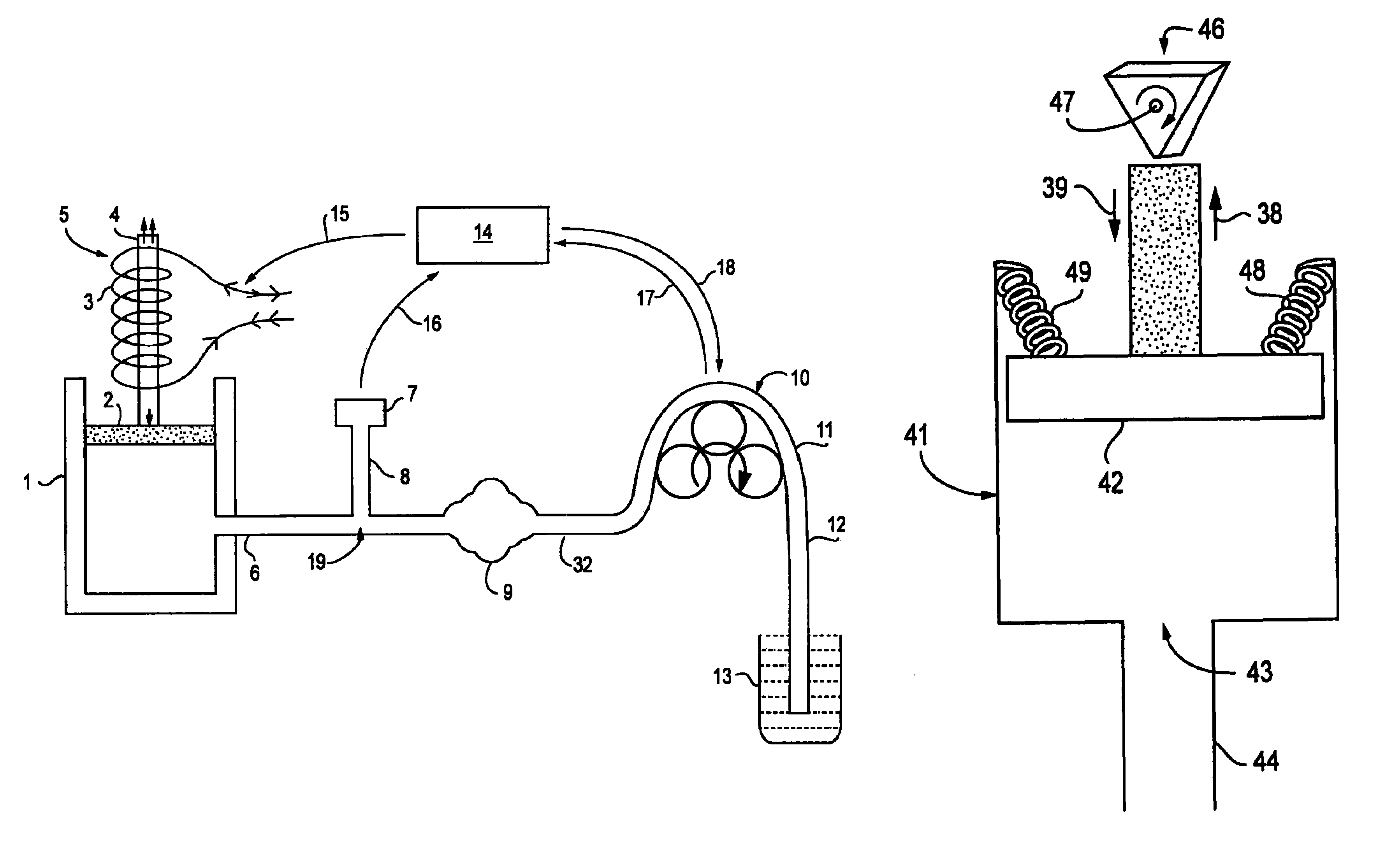
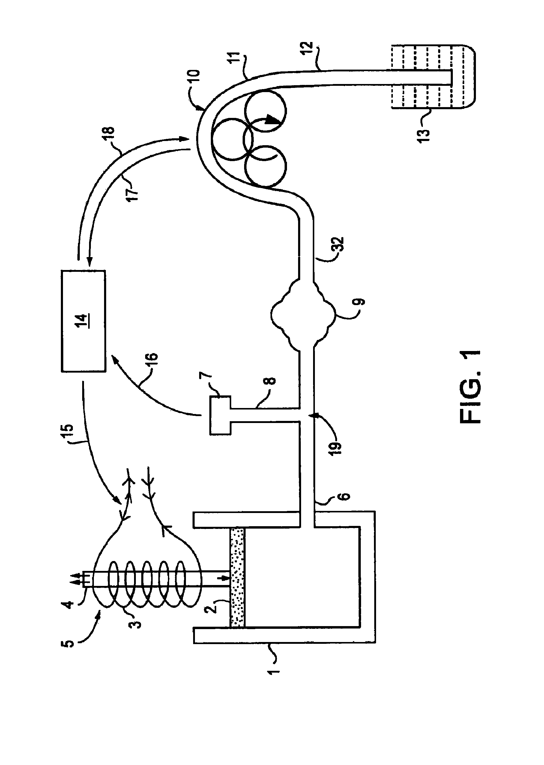
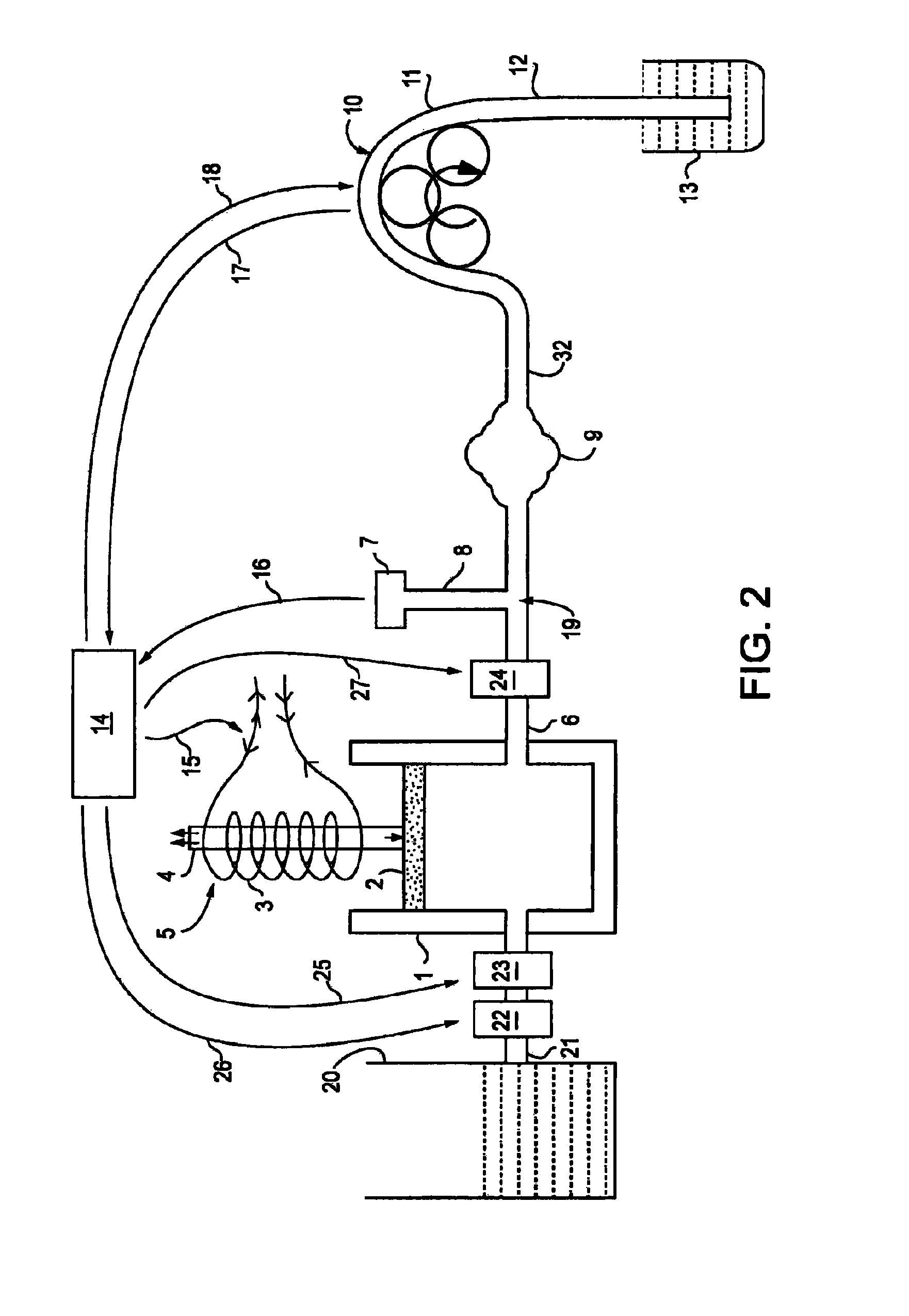
[0050]Accordingly, the present invention provides a system for distending body tissue cavities of subjects by continuous flow irrigation during endoscopic procedures the said system comprising: a syringe shaped fluid source reservoir containing a non viscous physiologic fluid meant for cavity distension; an outlet port of the syringe shaped fluid source reservoir being connectable to an inflow port of an endoscope instrument via an inflow tube for dispensing the fluid at a controlled flow rate into the cavity, the flow rate at which the fluid enters into the cavity being termed as the cavity inflow rate; an inflow pressure transducer being located anywhere in the inflow tube for measuring the fluid pressure inside the cavity, an outflow port of the endoscope being connectable to an inlet end of a variable speed positive displacement outflow pump through an outflow tube for removing the fluid from the cavity at a controlled flow rate, the flow rate of the said outflow pump being term...


PUM


Abstract

A system to minimize fluid turbulence inside a tissue cavity during endoscopic procedures. A body tissue cavity of a subject is distended by continuous flow irrigation using a solenoid operated pump on the inflow side and a positive displacement pump, such as a peristaltic pump, on the outflow side, such that the amplitude of the pressure pulsations created by the outflow positive displacement pump inside the said tissue cavity is substantially dampened to almost negligible levels. The present invention also provides a method for accurately determining the rate of fluid loss into the subject's body system during any endoscopic procedure without utilizing any deficit weight or fluid volume calculation, the same being accomplished by using two fluid flow rate sensors. The present invention also provides a system of creating and maintaining any desired pressure in a body tissue cavity for any desired cavity outflow rate.

Description

FIELD OF INVENTION[0001]The present invention relates to a system for distending body tissue cavities of subjects utilizing continuous flow irrigation during endoscopic procedures. The system and the methods of the present invention described above can be used in any endoscopic procedure requiring continuous flow irrigation few examples of such endoscopic procedures being hysteroscopic surgery, arthroscopic surgery, trans uretheral surgery (TURP), endoscopic surgery of the brain and endoscopic surgery of the spine. The proposed invention can also have certain useful non medical applications.BACKGROUND OF THE INVENTION[0002]Endoscopic surgery is becoming increasingly popular because of the following reasons:[0003](a) it is a minimally invasive form of surgery,[0004](b) it avoids large incisions over the skin and muscle,[0005](c) it is associated with less pain,[0006](d) there is a relatively less requirement of blood transfusions and[0007](e) the patients can return back to normal wo...

Claims


Application Information

Patent Timeline
Patent Type & Authority Patents(United States)
IPC IPC(8): A61M31/00
CPCA61M1/0058A61M3/0258A61M29/00A61M31/00A61M3/0216A61B1/015A61M2205/3334A61M1/77A61M3/0202
Inventor KUMAR
Owner KUMAR BV
Learn More