
Frequency-agile frequency-selective variable attenuator

a frequency-agile, variable technology, applied in the direction of electrical equipment, multiple-port networks, waveguides, etc., can solve the problems of affecting the reception of lower-level signals, affecting the performance of receivers, and raising the noise floor of receivers

Inactive Publication Date: 2012-11-06
THE UNITED STATES OF AMERICA AS REPRESENTED BY THE SECRETARY OF THE NAVY
View PDF14 Cites 14 Cited by
  • Summary
  • Abstract
  • Description
  • Claims
  • Application Information

AI Technical Summary

Benefits of technology

[0009]The invention in one embodiment is directed to tuning the attenuation of a “third-order”, six-resonator, microstrip absorptive bandstop filter—composed of a properly phased cascade of three “first-order” stages—with a 22% frequency tuning range and a 20 dB stopban...

Problems solved by technology

Allowing higher level signals into the receiver front-end unattenuated can compromise receiver performance and inhibit or interfere with the reception of lower level signals.
While such solutions can prevent larger signals from compressing or saturating the amplifier, they indiscriminately attenuate signal power across a broad band of frequencies—unavoidably attenuating weaker signals as well as stronger signals, raising the receiver noise floor, and introducing additional sources of signal distortion that significantly degrade the dynamic range of the receiver.
Conventional bandstop filters suffer significant performance degradation when tuned over a substantial frequency range, making conventional bandstop filter approaches undesirable for realizing frequency-agile frequency-selective attenuators.
While, due to their relative simplicity, “first-order” absorptive filters tend to be the most practical to use in frequency-agile applications, the attenuation characteristics of such first-order sections alone tend to lack sufficient stopband bandwidth to be of practical use.
A conventional bandstop filter approach to realizing this variable attenuation function is undesirable because the bandwidth of a conventional bandstop filter is dependent on the level of its stopband attenuation, so that varying one varies the other.
Consequently, the attenuation of stronger signals cannot currently be tailored to their specific power levels and receiver dynamic range is still compromised.

Method used


Image

  • Frequency-agile frequency-selective variable attenuator
  • Frequency-agile frequency-selective variable attenuator
  • Frequency-agile frequency-selective variable attenuator

Examples


Embodiment Construction

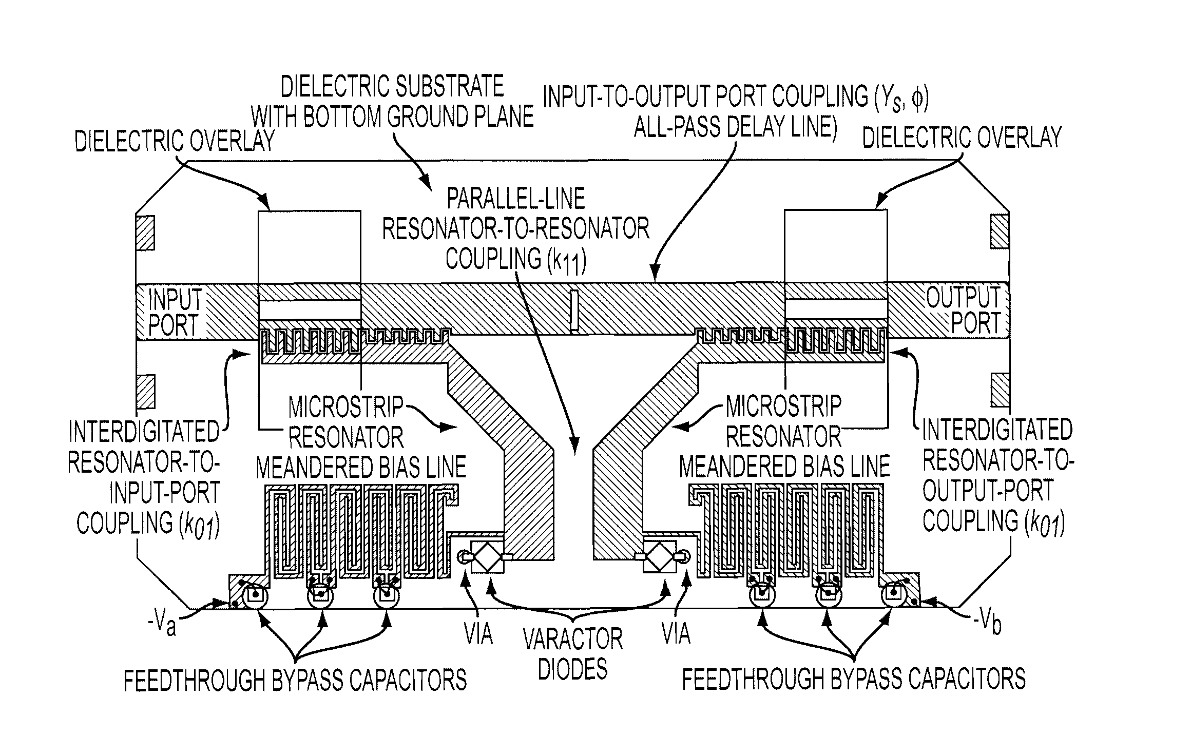
[0021]The invention is directed to a method of tuning absorptive bandstop filters—such as those disclosed in U.S. Pat. No. 7,323.955. Douglas R. Jachowski, issued Jan. 29, 2008, and incorporated herein by reference—so as to realize a frequency-agile frequency-selective variable attenuator.

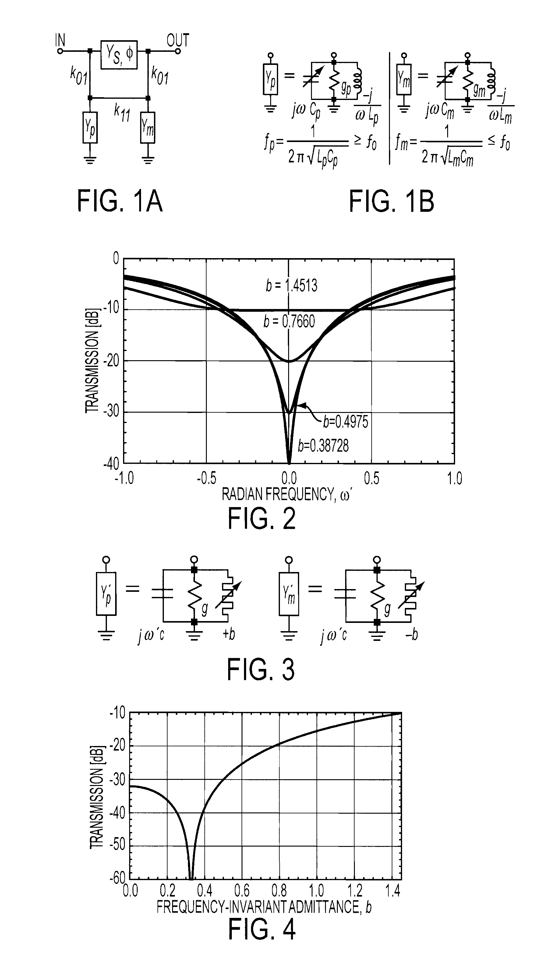
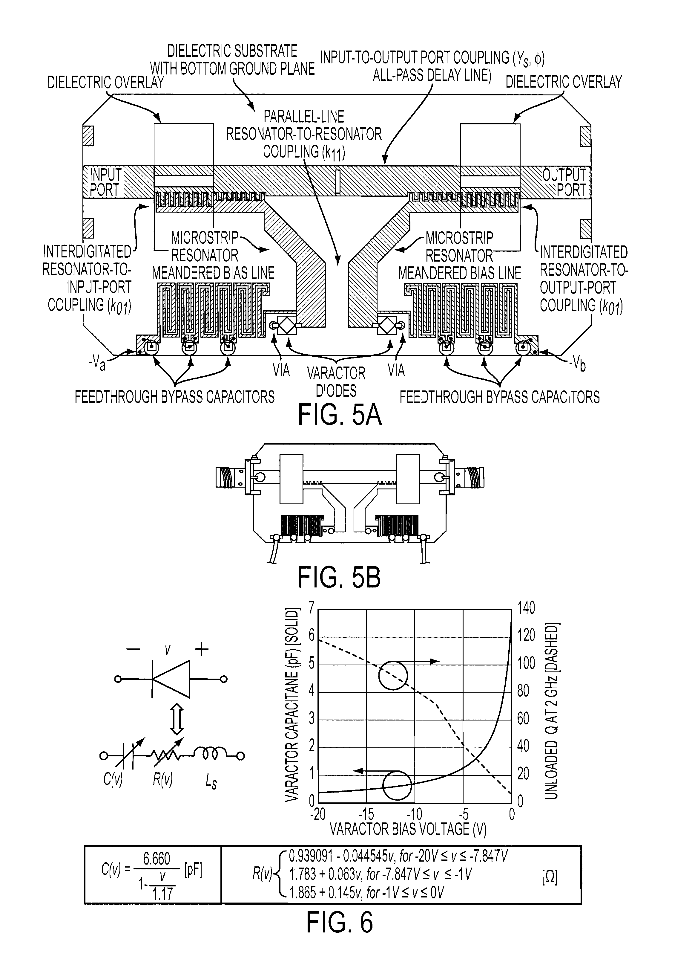
[0022]Conventional bandstop filters reflect stopband signals, and resonator loss tends to reduce and limit their stopband attenuation and band-edge selectivity. In Jachowski-2, a two-resonator bandstop filter topology, termed an “absorptive- pair”, is described that, at least to some extent, absorbs stopband signals—with resonator loss limiting minimum bandwidth rather than stopband attenuation. One of many possible electrically-equivalent circuit schematics of an absorptive pair bandstop filter is given in FIG. 1A, in which ideal (frequency invariant) admittance inverters k01 couple lossy lumped-element resonators, with admittances Yp and Ym, to the ends of a phase shift element of characteristic ...


PUM


Abstract

A method of tuning the stopband attenuation of an absorptive bandstop filter having at least a first and second resonator, where the first resonator includes a first tuning element that exhibits a first resonant frequency, the second resonator includes a second tuning element that exhibits a second resonant frequency, and the tuning elements are used to adjust the corresponding resonant frequencies, includes 1) adjusting the first resonant frequency using the first tuning element; and 2) adjusting the second resonant frequency using the second tuning element, such that both resonant frequencies are coordinated to obtain a selected stopband attenuation level and to thus realize a frequency-selective variable attenuator.

Description

CROSS-REFERENCE TO RELATED APPLICATIONS[0001]This Application claims the benefit of U.S. Provisional Application 61 / 185,218 filed on Jun. 9, 2009, and incorporated herein by reference.FIELD OF THE INVENTION[0002]The invention is directed to a means of creating a frequency-agile frequency-selective variable attenuator, or, from another point of view, a method of tuning the stopband attenuation level of a frequency-agile absorptive bandstop filter that preserves stopband bandwidths.BACKGROUND OF THE INVENTION[0003]Multi-function receivers for communication and navigation, as well as single-function receivers for communications, surveillance, or reconnaissance, are at times exposed to incident signals of interest having substantially different power levels. Allowing higher level signals into the receiver front-end unattenuated can compromise receiver performance and inhibit or interfere with the reception of lower level signals. Particularly strong signals could even drive the amplifie...

Claims


Application Information

Patent Timeline
IPC IPC(8): H01P1/20H01P5/18H01P1/212
CPCH01P1/2039H01P1/227H01P5/04
Inventor JACHOWSKI, DOUGLAS R
Owner THE UNITED STATES OF AMERICA AS REPRESENTED BY THE SECRETARY OF THE NAVY
Learn More