
Ophthalmic surgical cassette and system

a technology of ophthalmic surgery and cassette, which is applied in the direction of positive displacement liquid engines, suction drainage containers, machines/engines, etc., can solve the problems of difficult and time-consuming pulling such tubing off the barbs, and the precise level of fluids within the cassette is not consistently determined,

Active Publication Date: 2012-11-06
BAUSCH & LOMB INC
View PDF13 Cites 3 Cited by
  • Summary
  • Abstract
  • Description
  • Claims
  • Application Information

AI Technical Summary

Benefits of technology

The present invention is directed towards an improved ophthalmic surgical cassette and pump system. The invention addresses various issues that were previously present in prior art cassettes, such as inconsistent fluid level detection, difficulty in removing tubing from the cassette, and difficulty in aligning the cassette with the pump. The invention provides a venturi ophthalmic surgical cassette and pump system that addresses these issues. The invention includes a cassette with a venturi pump system that has a fluid level detection scheme to prevent the cassette from overflowing and leaking surgical fluids into the pump. The cassette has a majority of its interior volume of aspirant fluid and tissue flow from a surgery that can be disposed of easily. The invention also includes a detection scheme for the fluid level in the cassette, as well as a graphical illustration of the fluid level detection. The invention also includes an improved design for the cassette and pump system that makes it easier to insert the cassette into the pump and align it properly. Overall, the invention provides an improved ophthalmic surgical cassette and pump system that addresses various issues in prior art cassettes and pumps.

Problems solved by technology

Therefore, the precise level of fluids within a cassette is not consistently determined by such a float ball and light detector scheme.
Pulling such tubing off the barbs can be somewhat difficult and time consuming and is not easily accomplished.

Method used


Image

  • Ophthalmic surgical cassette and system
  • Ophthalmic surgical cassette and system
  • Ophthalmic surgical cassette and system

Examples


Embodiment Construction

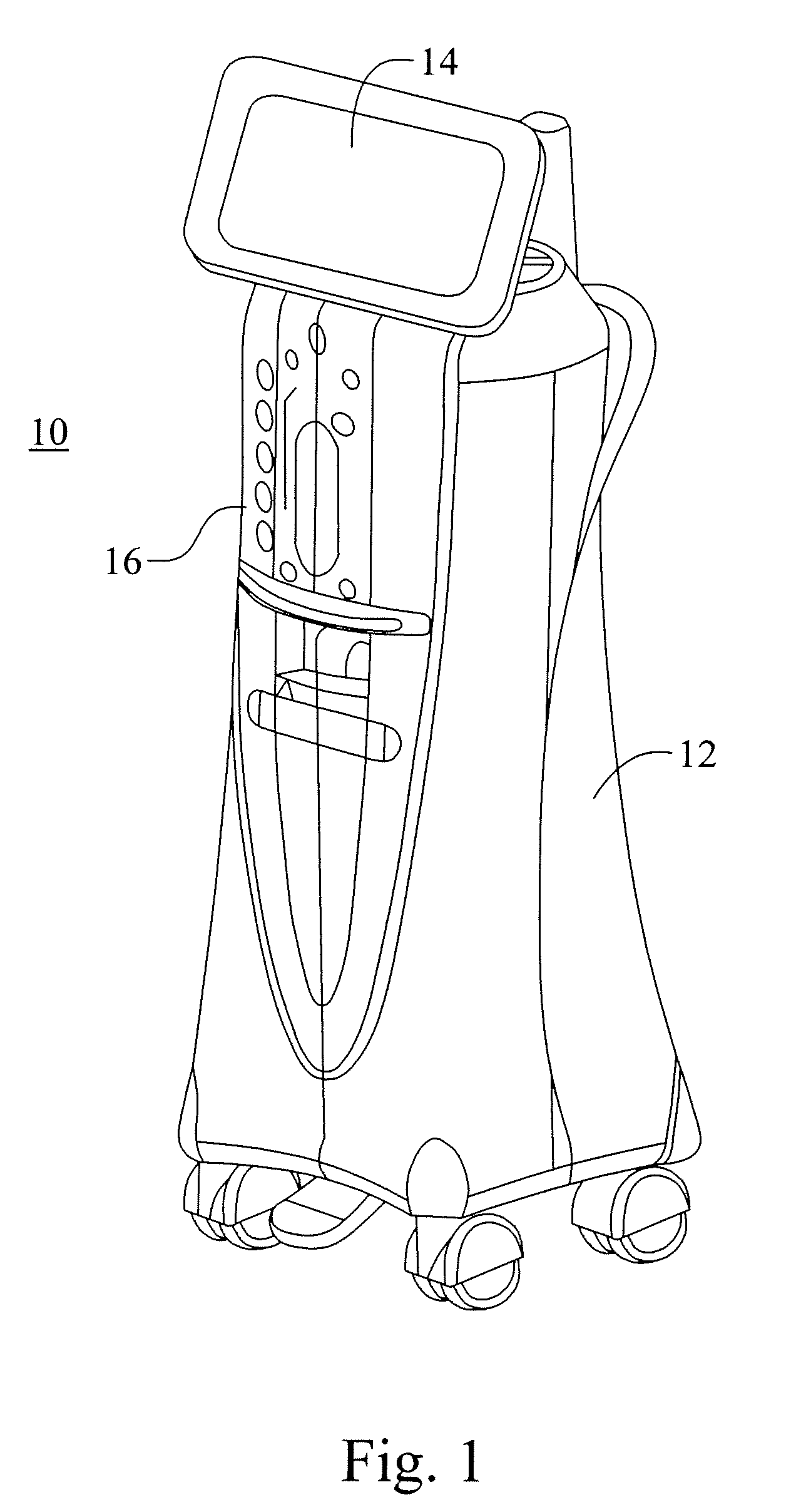
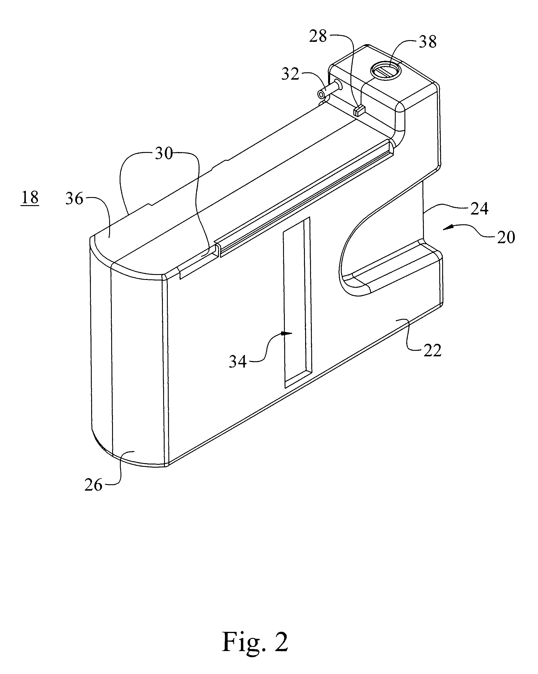
[0024]FIG. 1 shows a perspective view of an ophthalmic surgical console 10, in accordance with the present invention. Console 10 includes a body or chassis 12, a display 14, and a pump 16. Console 10 also may include an IV pole assembly, other ophthalmic surgical modules, such as a light module, scissors module, a second pump, and other typical ophthalmic surgical modules, all of which are not shown. A rigid walled container 18, with an interior volume described in detail below forms a part of a cassette for use with an ophthalmic surgery pump, such as pump 16, and is typically inserted into pump 16. The container is preferably formed of a transparent plastic material suitable for ophthalmic surgery, such as is well known in the art. Container or cassette 18 preferably includes at least one tapered alignment slot 20 formed in a side wall 22 of the container 18. The slot preferably extends from a back wall 24 towards a front wall 26. An irrigation manifold base (described in detail b...


PUM


Abstract

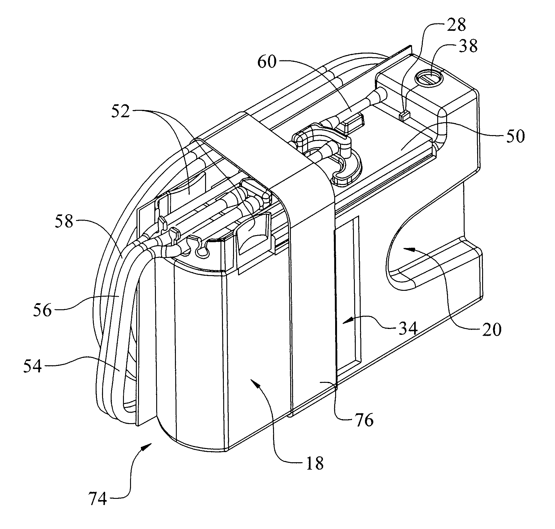
A cassette 74 for use with an ophthalmic surgical pump 16 for collecting aspirant fluid and tissue from a patient's eye includes a rigid walled container 18 having an interior volume 42. At least one tapered alignment slot 20 is formed in a side wall of the container 18 and extends from a back wall 24 towards a front wall 26. An irrigation and aspiration manifold base 50 is removeably attached to the container 18. An aspiration path 46 is formed within the container 18 for receiving the aspiration fluid and the tissue from the eye and directing the flow of fluid towards a front half of the container 18 before the fluid and tissue collects within a majority of the interior volume 42 of the container 18. A fluid level indicator 34 is formed on a wall 22 of the container 18, such that an associated photo-detector 86 of the pump 16 may determine a level of fluid in the container 18.

Description

BACKGROUND OF THE INVENTION[0001]This application claims the benefit of Provisional Patent Application No. 60 / 812,378 filed Jun. 10, 2006 which is incorporated by reference herein.[0002]1. Field of the Invention[0003]The present invention is directed towards an ophthalmic surgical cassette and pump system. More specifically, the present application is directed to a venturi ophthalmic surgical cassette and pump.[0004]2. Description of Related Art[0005]Ophthalmic surgical cassettes for use with various pump systems, including venturi pumps are well known in the art. Such surgical cassettes, particularly for use with the venturi pump, typically include a rigid walled cassette that can be connected to irrigation / aspiration tubing. In turn, the tubing is typically attached to a surgical handpiece for use by a surgeon during eye surgery. The rigid walled cassettes then have a majority of an interior volume of a cassette or container that collects aspirant fluid and tissue flow from a surg...

Claims


Application Information

Patent Timeline
Patent Type & Authority Patents(United States)
IPC IPC(8): A61M37/00F04B43/12F04B45/06F04B43/08
CPCA61M1/0005A61M1/0049A61M1/0058A61F9/007A61M2210/0612A61M2205/123A61M2205/3306A61M2205/3389A61M2205/6063A61M1/0076A61M1/63A61M1/78A61M1/804A61M1/77A61M3/0201A61M1/72A61M1/00
Inventor WALTER, JONATHAN T.ASKEW, MIKE
Owner BAUSCH & LOMB INC
Learn More