Continuous geomechanically stable wellbore trajectories

a geomechanically stable, wellbore technology, applied in the direction of directional drilling, force/torque/work measurement apparatus, instruments, etc., can solve the problems of inability to improve the wellpath solution provided, heuristic and manual determination of the solution, and the process is relatively slow, so as to reduce the time of production and the effect of less prone to errors

Active Publication Date: 2012-10-30
SCHLUMBERGER TECH CORP +1
View PDF40 Cites 8 Cited by
  • Summary
  • Abstract
  • Description
  • Claims
  • Application Information

AI Technical Summary

Benefits of technology

[0009]Relative to trajectory calculation workflows described in the Background, the invention advantageously automates trajectory calculation, either partially or completely. Consequently, suitable results tend to be less time consuming to produce and less prone to error. One practical implication is that the selected trajectory is more likely to be continuously geomechanically stable.

Problems solved by technology

Note that this does not improve the wellpath solution provided by the pre-processing step, but rather helps to compensate for deviation from an optimal wellpath solution by calculating drilling mud weight requirements to prevent failure of the least geomechanically stable positions.
One of the drawbacks of the two-step workflow described above is that solutions are heuristic and determined manually.
This process is relatively slow because it is manual.
Further, the process is heuristic because the relative strengths of different potential trajectories may not be apparent to the engineer without some analysis, i.e., the engineer cannot pick the best trajectory out of the data, but rather picks various potential trajectories for comparison.
As a result, the selected wellpath may be far from optimal.

Method used


Image

  • Continuous geomechanically stable wellbore trajectories
  • Continuous geomechanically stable wellbore trajectories
  • Continuous geomechanically stable wellbore trajectories

Examples


Embodiment Construction

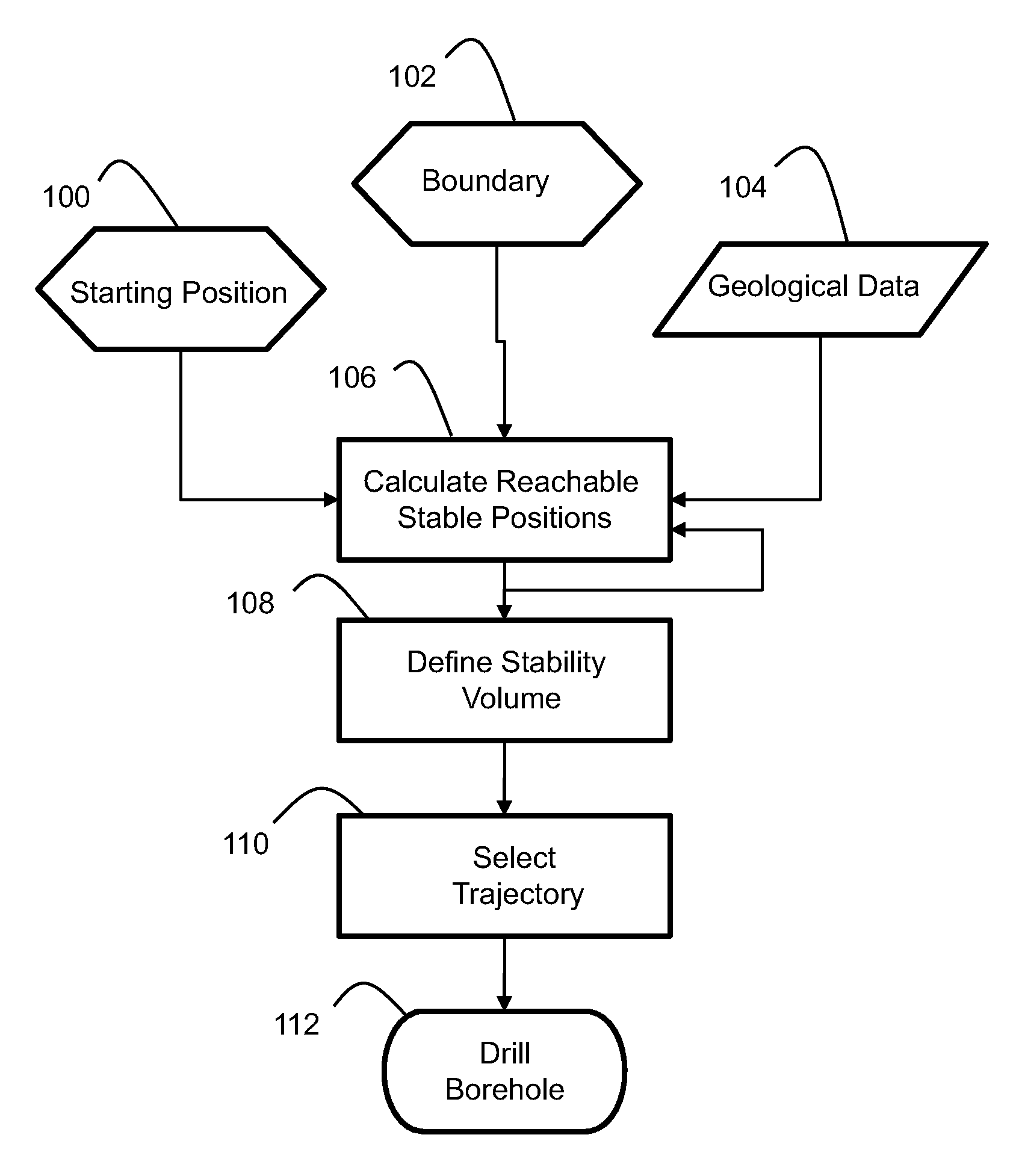
[0019]FIG. 1 illustrates general steps of a method for selecting and drilling a borehole having a continuous geomechanically stable trajectory. Some or all of the steps may be implemented by a computer, or with the assistance of a computer. As such, at least some of the steps may be embodied in a computer program product stored on a computer-readable medium.

[0020]Referring now to FIGS. 1 and 2a through 2c, a starting position 100, boundary volume 102 and geological data 104 are provided as initial inputs. Based on those inputs, a stability navigation algorithm is employed to compute a set of reachable stable positions relative to the starting position as indicated by step 106. In particular, the reachable stable positions are constrained by both the boundary volume 102 and a geological model defined by the extent of available geological data, and stability is determined as a function of the geological data. This step 106 may be repeated over multiple iterations by using the reachabl...


PUM


Abstract

A continuous geomechanically stable trajectory in a subterranean formation is found by calculating at least one reachable stable position relative to a starting position based on geological data indicative of characteristics of the subterranean formation, and iteratively utilizing the calculated reachable stable position as a new starting position. The calculation may be constrained by a boundary including selected distance and direction relative to the starting position, and selected rate of angle change. Within the constraints of the boundary, the possible new trajectories considered may be discretized. The result of the calculations is a three dimensional tree which defines a stability volume. Pruning of at least some branches of the tree may be employed so that not all stable positions have the preselected number of branches, thereby helping to elongate the tree. Either or both of the tree and stability volume are used to select at least one trajectory. For example, the trajectory may be selected from sets of interconnected stable wellbore positions, or based on some other criteria constrained by the stability volume. The trajectory is then used as the basis for drilling a borehole.

Description

FIELD OF THE INVENTION[0001]This invention is generally related to borehole trajectory selection, and more particularly to calculation and selection of continuous geomechanically stable wellbore trajectories.BACKGROUND OF THE INVENTION[0002]The integration of geomechanics and wellpath design is currently a subject of various research efforts. Generally, the proposals published to date are modified workflows which incorporate stability analysis within the overall process of determining well trajectory for a given situation. Such modified workflows attempt to reconcile the different, and sometimes contradictory, goals of achieving borehole stability and reaching one or more positions at different depths in a formation. Currently, the state of the art is a workflow that combines the two problems by executing a pre-processing step and a post-processing step.[0003]The pre-processing step includes calculation of a subset of geometric conditions which satisfy user-defined stability criteri...

Claims


Application Information

Patent Timeline
Patent Type & Authority Patents(United States)
IPC IPC(8): G01V11/00G01B5/30G06G7/48
CPCE21B7/04E21B44/00
Inventor HERRERA, ADRIAN ENRIQUE RODRIQUEZ
Owner SCHLUMBERGER TECH CORP
Why Eureka
Try Eureka