
Directional jet flow control

a flow control and directional jet technology, applied in the direction of mechanical equipment, lighting and heating apparatus, combustion types, etc., can solve the problems of difficult uniform coating, difficult to achieve uniform coating, and difficult to control the flow rate of the directional jet, so as to improve the thermal spray process, improve the effect of thermal spraying and reduce the temperatur

Inactive Publication Date: 2012-10-30
UTAH STATE UNIVERSITY
View PDF6 Cites 5 Cited by
  • Summary
  • Abstract
  • Description
  • Claims
  • Application Information

AI Technical Summary

Benefits of technology

Enables precise and high-frequency control of jet direction and profile over large surfaces with a single nozzle, reducing substrate heating and improving thermal spray processes by mitigating intense heat distribution and maintaining long-term operation in hostile conditions.

Problems solved by technology

In many of these processes, such as thermal sprays, the contents of the jet or spray are combusting, making the environment in which the jet operates very hostile.
Control schemes that rely on vectoring of the jet nozzle would place moving parts in this hostile environment, where they would wear quickly, and be severely limited in slew rate.
Additionally, it is difficult to coat evenly in this manner.
The hardware required to effect these changes is unreliable and heavy and thus slow.
However, it is difficult to reliably generate the required oscillatory blowing.
Currently, expensive robots are commonly used for this purpose.
Thermal spray processes typically result in very high material cooling rates (>106 K / s).
Due to the high temperature combustion environment present in or near these process nozzles, mechanical vectoring of the nozzle is not feasible since this would place moving parts in the jet flow, reduce device durability, and severely limit directional frequency response.
Furthermore, traversing a part to be coated, which is often heated to high temperatures, is costly.
This results in excessive heating of the substrate.
This is currently being investigated as a method for thrust-vectoring of fighter aircraft, although the hardware required to effect these changes is unreliable and heavy (and thus slow).
However, it is difficult to reliably generate the required oscillatory blowing.
Unfortunately, schemes involving suction prohibit use in hostile environments such as combustion since hot and / or corrosive gas would be drawn into the suction slot.

Method used


Image

  • Directional jet flow control
  • Directional jet flow control
  • Directional jet flow control

Examples


Embodiment Construction

[0021]In the following description, numerous specific details are provided for a thorough understanding of specific preferred embodiments. However, those skilled in the art will recognize that embodiments can be practiced without one or more of the specific details, or with other methods, components, materials, etc. In some cases, well-known structures, materials, or operations are not shown or described in detail in order to avoid obscuring aspects of the preferred embodiments. Furthermore, the described features, structures, or characteristics may be combined in any suitable manner in a variety of alternative embodiments. Thus, the following more detailed description of the embodiments of the present invention, as represented in the drawings, is not intended to limit the scope of the invention, but is merely representative of the various embodiments of the invention.

[0022]This disclosure presents a new directional jet flow control device that utilizes an adjustable flow-control me...


PUM

PropertyMeasurementUnit
cross-section dimensionaaaaaaaaaa
pressureaaaaaaaaaa
dimensionaaaaaaaaaa

Abstract

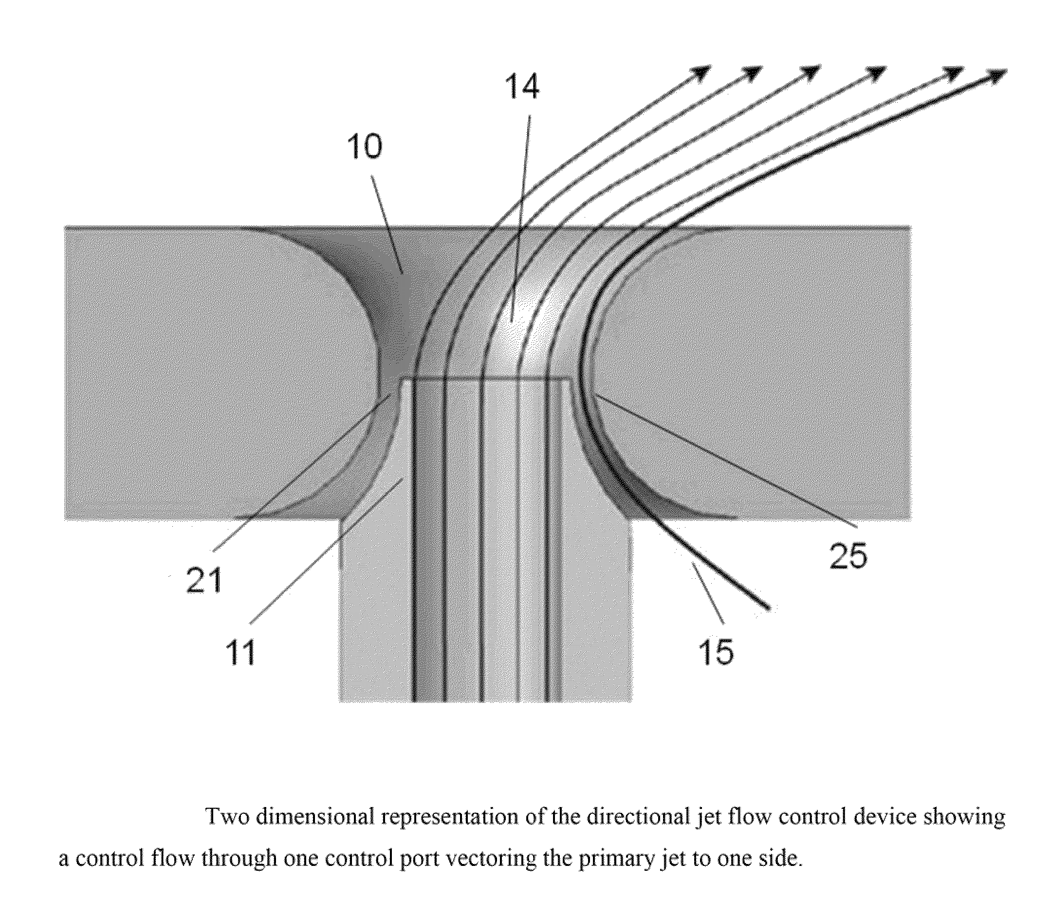
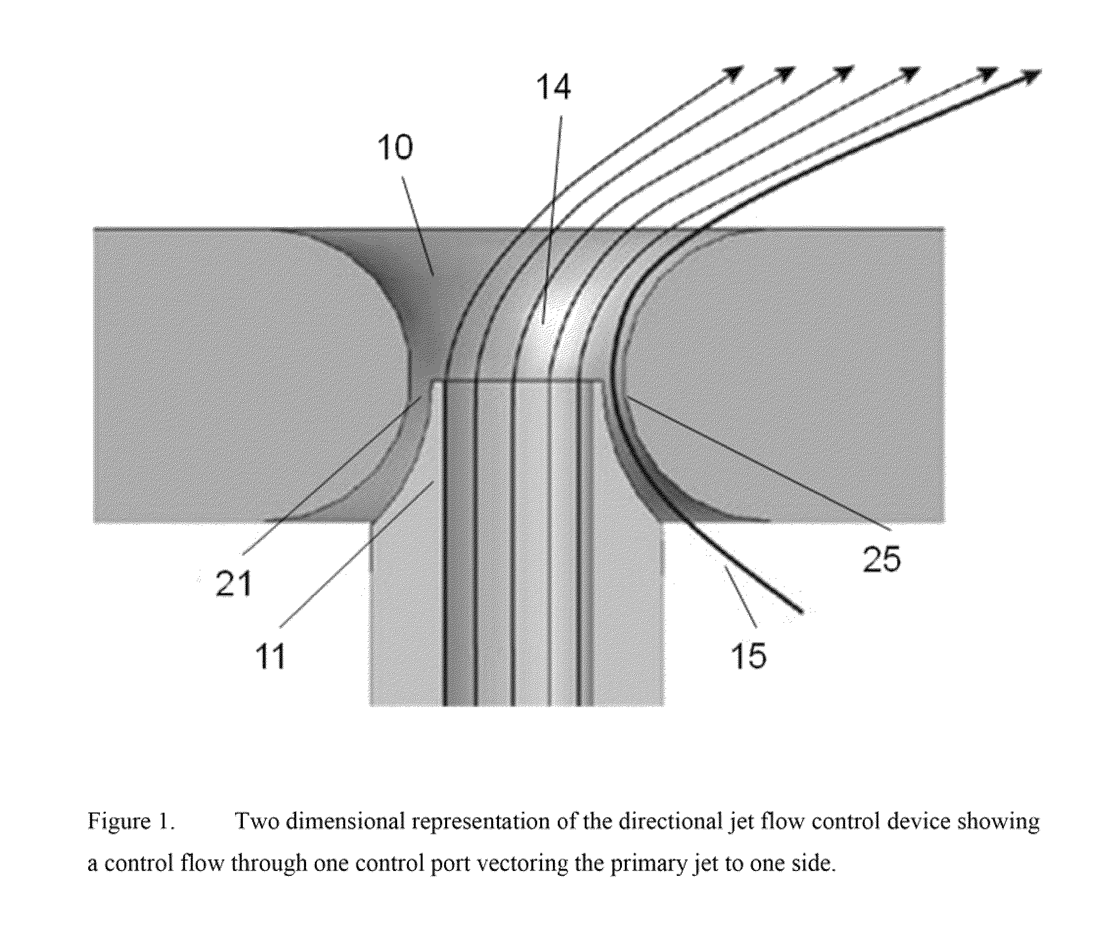
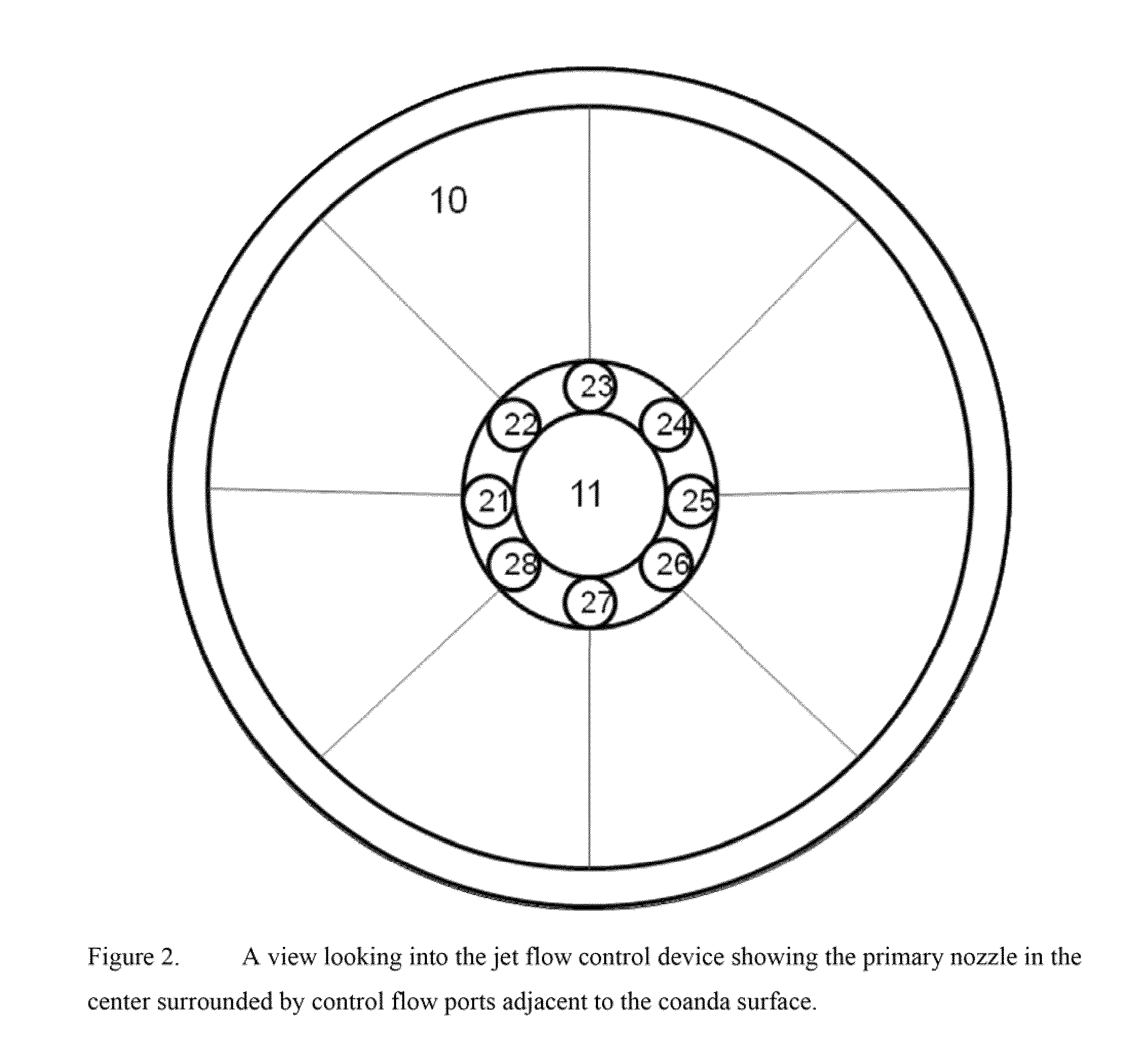
A device is disclosed that uses a flow-control methodology to control sprays at very high precision and frequency. The device is based on an enhanced Coanda effect. The control flow is selectively applied to the region in which we desire the jet to vector and control the profile (width) of the jet. The control flow is introduced through multiple control flow ports surrounding the primary nozzle and adjacent to the Coanda surface. By selectively opening and closing different control flow ports the motion and profile of the jet can be controlled.

Description

RELATED APPLICATIONS[0001]This application is a Continuation-in-part of U.S. patent application Ser. No. 11 / 637,443 filed on Dec. 11, 2006, entitled “High-Speed Jet Control” which claims priority to U.S. Provisional Application No. 60 / 749,202 filed on Dec. 9, 2005, entitled “High-Speed Jet Control”, both of which are incorporated herein by reference.TECHNICAL FIELD[0002]The present invention relates to methods and devices for directing and controlling high-speed fluid jets and thermal sprays.BACKGROUND[0003]There are many processes that can benefit from the ability to precisely vector a jet and to control its width. These include thin-film coating processes in which it is vitally important that the film thickness be uniform, even if the surface to be coated is not flat. In many of these processes, such as thermal sprays, the contents of the jet or spray are combusting, making the environment in which the jet operates very hostile. Control schemes that rely on vectoring of the jet no...

Claims


Application Information

Patent Timeline
Patent Type & Authority Patents(United States)
IPC IPC(8): B05B17/04B05B7/06B05B7/04F23D11/16F23D11/10
CPCB05B7/08C23C24/04F15D1/06F23D14/48C23C4/12B05B1/12B05B7/0815B05B7/201F23D2900/14481B05B7/222B05B1/08F15D1/08
Inventor SMITH, BARTON L.SMITH, RYAN
Owner UTAH STATE UNIVERSITY
Learn More