Eureka AIR delivers breakthrough ideas for toughest innovation challenges, trusted by R&D personnel around the world.

Compressor with controllable recirculation and method therefor

a compressor and controllable technology, applied in the field of compressor systems, can solve the problems of surge, flow separation and/or stalling of the blades, and the surge of the compressor

Inactive Publication Date: 2012-10-16
HONEYWELL INT INC
View PDF6 Cites 52 Cited by
  • Summary
  • Abstract
  • Description
  • Claims
  • Application Information

AI Technical Summary

Problems solved by technology

Compressor surge refers to a generally undesirable operating condition in which the flow begins to separate on the compressor blades because of excessive incidence angle.
For example, compressor surge can occur when the engine is operating at high load or torque and low engine speed, or when the engine is operating at a low engine speed with a high rate of exhaust gas recirculation from the engine exhaust side to the intake side.
Additionally, surge can occur when a quick boosting response is required using an electrically assisted turbocharger and / or variable nozzle turbine (VNT) turbocharger, or when the engine is suddenly decelerated, e.g., if the throttle valve is closed while shifting between gears.
As a result of any of the foregoing operating conditions, the compressor can surge as the axial component of absolute flow velocity entering the compressor is, low in comparison to the blade tip speed in the tangential direction, thus resulting in the blades of the compressor operating at a high incidence angle, which leads to flow separation and / or stalling of the blades.
Compressor surge can cause severe aerodynamic fluctuation in the compressor, increase the noise of the compressor, and reduce the efficiency of the compressor.
In some cases, compressor surge can result in damage to the engine or its intake pipe system.

Method used


Image

  • Compressor with controllable recirculation and method therefor
  • Compressor with controllable recirculation and method therefor
  • Compressor with controllable recirculation and method therefor

Examples


Embodiment Construction

[0021]The present invention now will be described more fully hereinafter with reference to the accompanying drawings, in which some, but not all embodiments of the invention are shown. Indeed, this invention may be embodied in many different forms and should not be construed as limited to the embodiments set forth herein; rather, these embodiments are provided so that this disclosure will satisfy applicable legal requirements. Like numbers refer to like elements throughout.

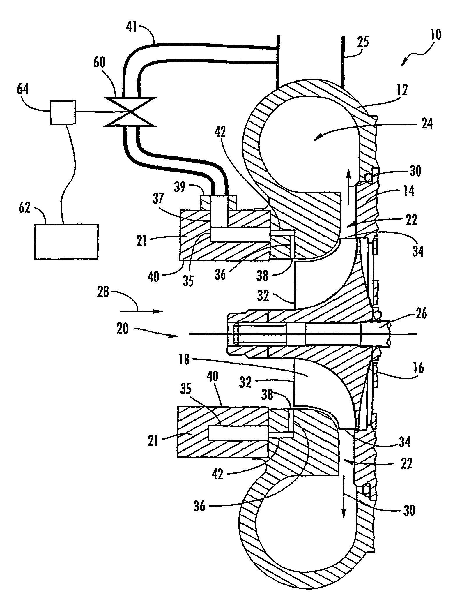
[0022]Referring now to the figures and, in particular, FIG. 1, there is shown a compressor 10 according to one embodiment of the present invention. The compressor 10 can be used in a turbocharger, e.g., to provide compressed intake air for an internal, combustion engine in a vehicle. Alternatively, the compressor 10 can be used in other devices and / or for compressing gases other than air. Thus, while the operation of the compressor 10 is described below as compressing air for use in an internal combustion engine, ...


PUM


Abstract

There is provided a compressor (10) and an associated method for controlling a recirculation flow to control surging in the compressor. The compressor includes a housing (12) and a compressor wheel (16) mounted therein. A recirculation passage (41) receives compressed air from the compressor and recirculates the compressed air to an inlet passage (20) of the housing and, in particular, to leading edges (32) of blades (18) of the compressor wheel. An adjustable flow control device (60) is configured to control the flow of the compressed air through the recirculation passage to control a surge characteristic of the compressor. For example, the flow control device can include one or more valves (V1, V2, V3), each of which can be adjusted by an actuator (64).

Description

FIELD OF THE INVENTION[0001]The present invention relates generally to compressor systems, such as a compressor for use in a turbocharger for an internal combustion engine, and more particularly relates to controllable recirculation in such a compressor to prevent or reduce the occurrence of surging.BACKGROUND OF THE INVENTION[0002]Turbochargers are typically used to increase the power output of an internal combustion engine such as in an automobile or other vehicle. A conventional turbocharger includes a turbine and a compressor. The turbine is rotatably driven by the exhaust gas from the engine. A shaft connects the turbine to the compressor and thereby rotates the compressor. As the compressor rotates, it compresses air that is then delivered to the engine as intake air. The increase in pressure of the intake air increases the power output of the engine. In a typical turbocharger for an internal combustion engine of an automobile, the compressor is a centrifugal compressor, i.e.,...

Claims


Application Information

Patent Timeline
Patent Type & Authority Patents(United States)
IPC IPC(8): F04D29/66F04D27/02
CPCF04D27/0215F04D27/0223F05D2220/40
Inventor GU, RONGLEIYASHIRO, MASAHIKO
Owner HONEYWELL INT INC
Why Eureka
Eureka Blog
Learn More