
Method and system for monitoring the efficiency and health of a hydraulically driven system

a technology of hydraulic drive and efficiency monitoring, which is applied in the direction of seismology, instruments, nuclear elements, etc., can solve the problems of reducing the ability of tongs of the same make and model to react consistently, difficulty in consistently achieving properly tightened joints, and affecting the efficiency of hydraulic drive systems

Active Publication Date: 2012-10-02
KEY ENERGY SERVICES
View PDF57 Cites 23 Cited by
  • Summary
  • Abstract
  • Description
  • Claims
  • Application Information

AI Technical Summary

Problems solved by technology

However, properly tightened joints can be difficult to consistently achieve due to numerous rather uncontrollable factors and widely varying specifications of sucker rods.
Even supposedly identical tongs of the same make and model may have different operating characteristics, due to the tongs having varying degrees of wear on their bearings, gears, or seals.
Furthermore, as tongs system components age, their ability to react consistently is reduced.
Also, the amount of speed generated on an elongated member by a tongs drive based on a constant current level transmitted to the hydraulic valves in the tongs drive system decreases over time as components wear out.
Because the system does not react consistently over time, it is difficult to develop a static system that can effectively tighten elongated members over the life of the tongs.
The problem is that this time delay between the stop command being issued and the rod actually stopping is quite short, on the order of 10 milliseconds, and is influenced by changes in temperature.
As temperature of the hydraulic fluid increases, viscosity decreases, and the tongs motor is less efficient (conveys less torque, or energy for given flow and pressure).

Method used


Image

  • Method and system for monitoring the efficiency and health of a hydraulically driven system
  • Method and system for monitoring the efficiency and health of a hydraulically driven system
  • Method and system for monitoring the efficiency and health of a hydraulically driven system

Examples


Embodiment Construction

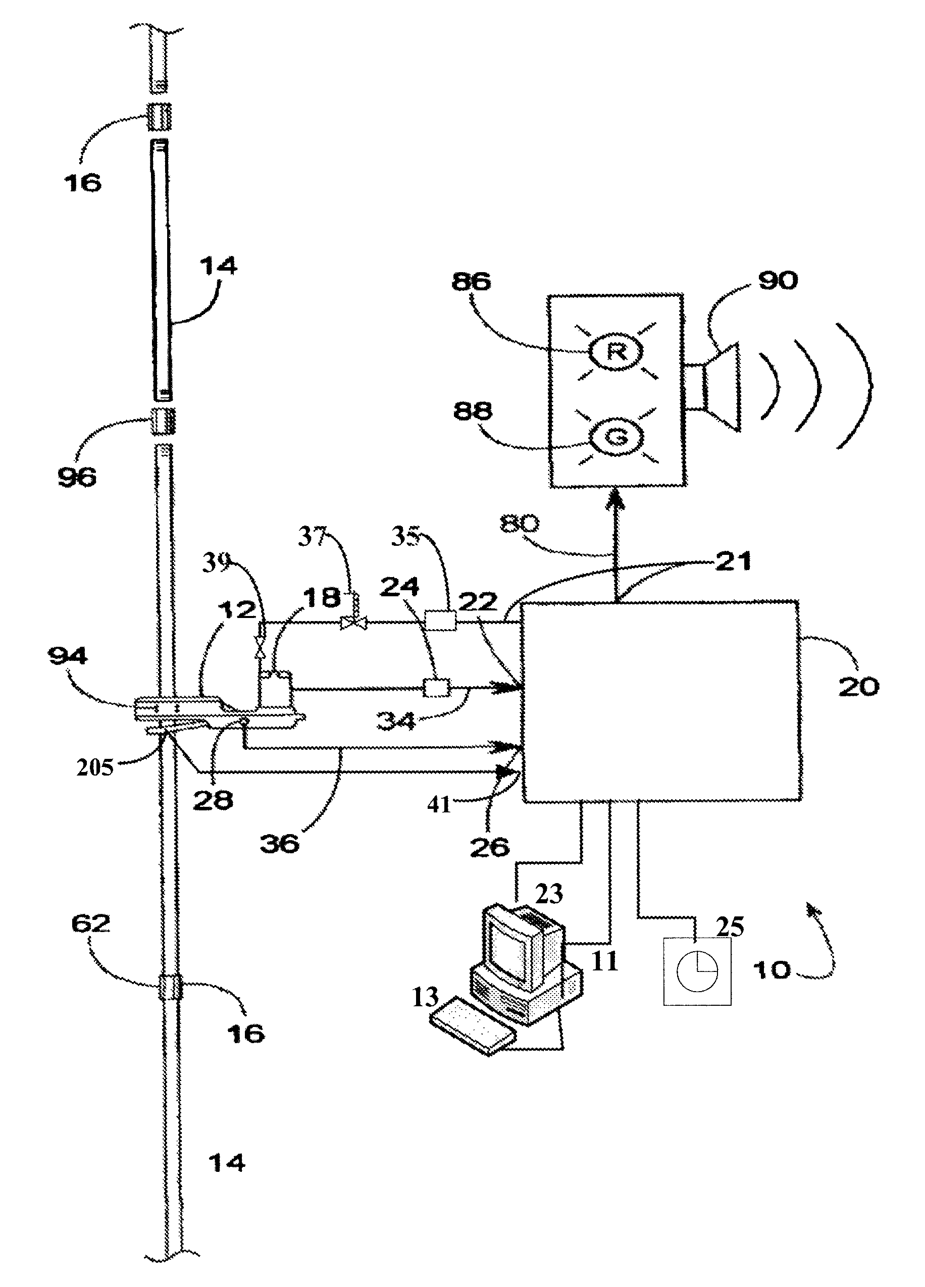
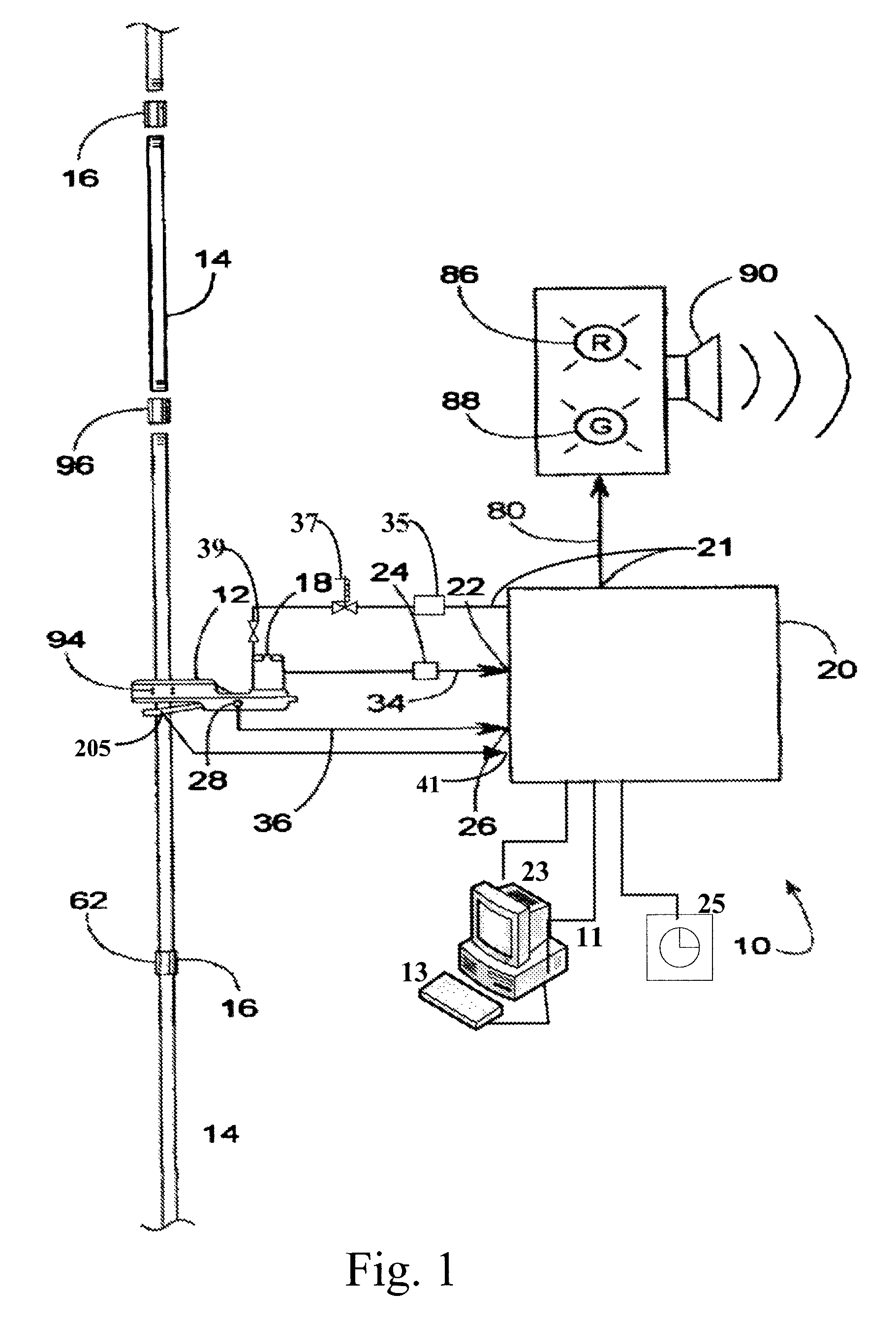
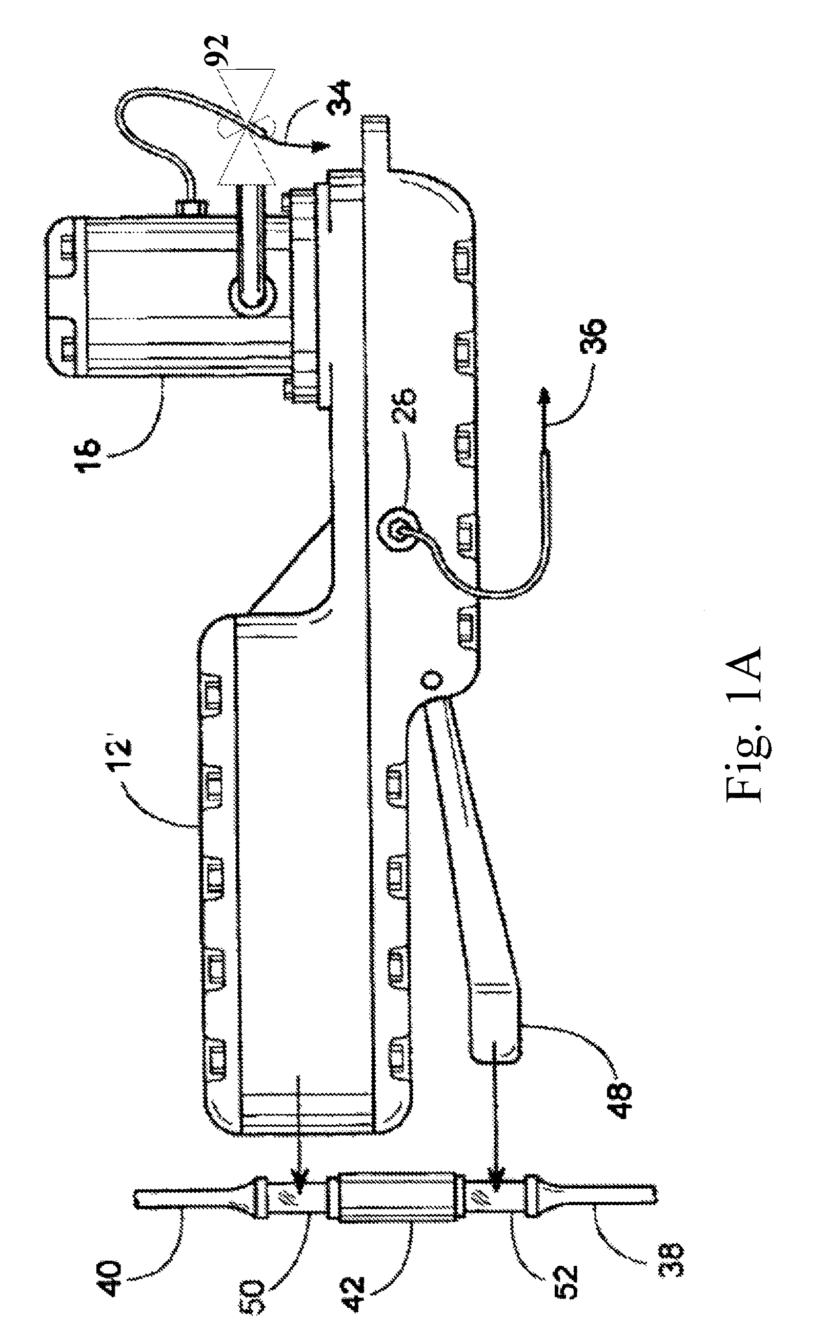
[0026]The present invention supports a tongs-based system and methods for monitoring operational aspects of a set of tongs during make-up and breakout to identify efficiency losses prior to a system failure. The present invention further supports modifying operational aspects based on temperature variables during a make-up or breakout process for rods and other elongated members, such at tubulars and other oil well equipment having threaded connections. Exemplary embodiments of the present invention can be more readily understood by reference to the accompanying figures. While the exemplary embodiments described in the figures will be discussed with referent to a make-up process, the same or substantially similar methods could be used to evaluate system performance and modify operational aspects during a breakout process for rods and other elongated members, and such breakout processes are within the scope and spirit of the present invention. The detailed description that follows is...


PUM


Abstract

Efficiency of a hydraulically driven system is evaluated by monitoring the change in ratio of output torque to input hydraulic pressure. The hydraulic pressure data is received from a hydraulic sensor. The torque data is received from a load cell receiving a force transmitted to it by a back-up wrench. Filters are applied to the data to obtain peak levels of torque and hydraulic pressure. A ratio is generated for each process associated with a rod or other elongated member based on peak torque and hydraulic pressure levels achieved during the process. The ratio is stored and compared to historical ratios to determine if the ratio has changed more than a predetermined amount over time. A similar evaluation can be achieved by comparing speed generated on the elongated member by the hydraulically driven system to the current level controlling the flow of hydraulic fluid to the hydraulically driven system.

Description

STATEMENT OF RELATED PATENT APPLICATION[0001]This non-provisional patent application claims priority under 35 U.S.C. §119 to U.S. Provisional Patent Application No. 61 / 118,493, titled Method and System for Monitoring the Health of a Tongs System, filed Nov. 28, 2008. This provisional application is hereby fully incorporated herein by reference.FIELD OF THE INVENTION[0002]The current invention generally relates to assembling threaded sucker rods and tubulars of oil wells and other wells. More specifically, the invention pertains to methods for monitoring operational aspects of a hydraulically driven system to identify efficiency losses prior to a system failure.BACKGROUND OF THE INVENTION[0003]Oil wells and many other types of wells often comprise a well bore lined with a steel casing. A casing is a string of pipes that are threaded at each end to be interconnected by a series of internally threaded pipe couplings. A lower end of the casing is perforated to allow oil, water, gas, or ...

Claims


Application Information

Patent Timeline
Patent Type & Authority Patents(United States)
IPC IPC(8): G01V1/40
CPCE21B19/165
Inventor CONQUERGOOD, STEVELORD, DAVID
Owner KEY ENERGY SERVICES
Learn More