Guide rail of a linear guide

a technology of linear guide rails and guide rails, which is applied in the direction of sliding contact bearings, manufacturing tools, instruments, etc., can solve the problems of limited longitudinal displaceability of the further guide carriages arranged on the guide rails

Inactive Publication Date: 2012-10-02
SCHAEFFLER TECH AG & CO KG
View PDF8 Cites 5 Cited by
  • Summary
  • Abstract
  • Description
  • Claims
  • Application Information

AI Technical Summary

Benefits of technology

[0004]The object of the present invention is to specify a guide rail, in which the disadvantage indicated above is avoided.
[0005]The object is achieved, according to the invention, by the guide rail which has, a plurality of guide carriages that can be moved one behind the other along the guide rail, without a collision or impact of the further guide carriage with the holder of the material measure occurring. The holder is fastened releasably at locations on the guide rail which lie outside the guide surfaces of the guide rail. The shape of the holder itself may be such that it lies outside a clearance profile of the guide carriage. The groove walls or the wall delimiting the hole are preferably oriented perfectly at right angles to the longitudinal axis of the guide rail. When the spreading means, formed, for example, by wedges, come to bear closely, while spreading open, against the groove walls or the wall of the hole, a perfect orientation of the holder of the guide rail can thus be assisted.
[0008]In a particular exemplary embodiment for the releasable fastening of the holder on the guide rail, the spreading means have cooperating wedges, one of which is arranged fixedly to the holding arm and another of which is arranged moveably with respect to the one wedge. The wedges cooperate such that they come to bear in the groove against the groove walls of the latter and are pressed onto these. The wedges can bear with their mutually confronting wedge surfaces one against the other and can be braced with one another in the groove of the guide rail via a tension screw. By the tension screw being turned, the two wedges are displaced along their wedge surfaces and come to bear with their tension surfaces against groove walls of the groove. The one wedge may in this case be connected in one piece to the holding arm. The tension surfaces, facing away from one another, of the wedges are preferably arranged at right angles to the supporting surface of the holding arm, so that a satisfactory positioning of the holder and therefore for satisfactory positioning of the material measure with respect to the guide rail are possible.
[0010]For the simple introduction of the wedges, the groove in the foot region of the guide rail may advantageously be designed as a transverse groove arranged transversely with respect to the longitudinal axis of the guide rail. The wedges can consequently be inserted into the open transverse groove from below in a simple way.

Problems solved by technology

One disadvantage of a holder of this type may be seen in that a further guide carriage which is arranged on the guide rail is limited in its longitudinal displaceability by the arrangement of the two holding brackets which surround the guide rail.

Method used


Image

  • Guide rail of a linear guide
  • Guide rail of a linear guide
  • Guide rail of a linear guide

Examples


Embodiment Construction

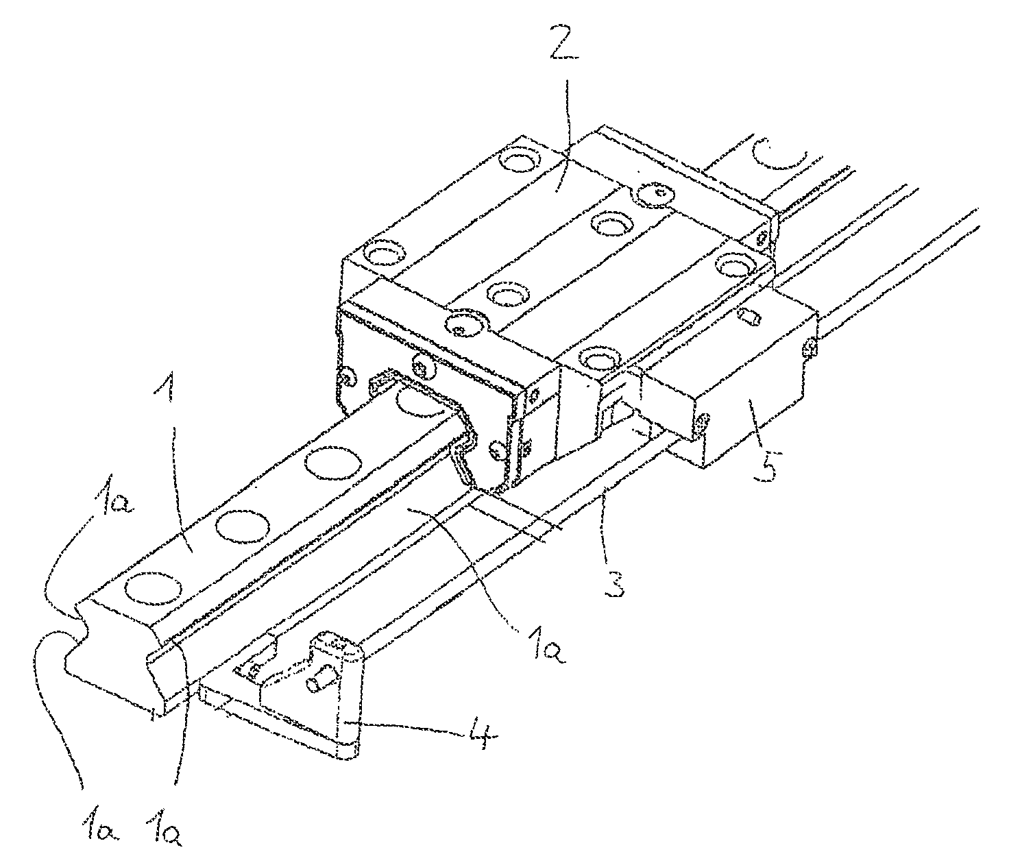
[0019]A guide rail according to the invention is depicted in FIGS. 1 to 4. FIG. 1 shows the guide rail 1 with a mounted guide carriage 2. The guide carriage 2 is guided and mounted on guide surfaces 1a of the guide rail 1. Furthermore, a material measure 3 is provided, which is fastened releasably to the guide rail 1 via holders 4. Only one holder 4 is depicted in FIG. 1.

[0020]It can be gathered from FIG. 1 that a measuring head 5 is attached to the guide carriage 2, the measuring head 5 cooperating in a known manner with the material measure 3 so that predetermined positions on the guide rail can be moved up to in a controlled way.

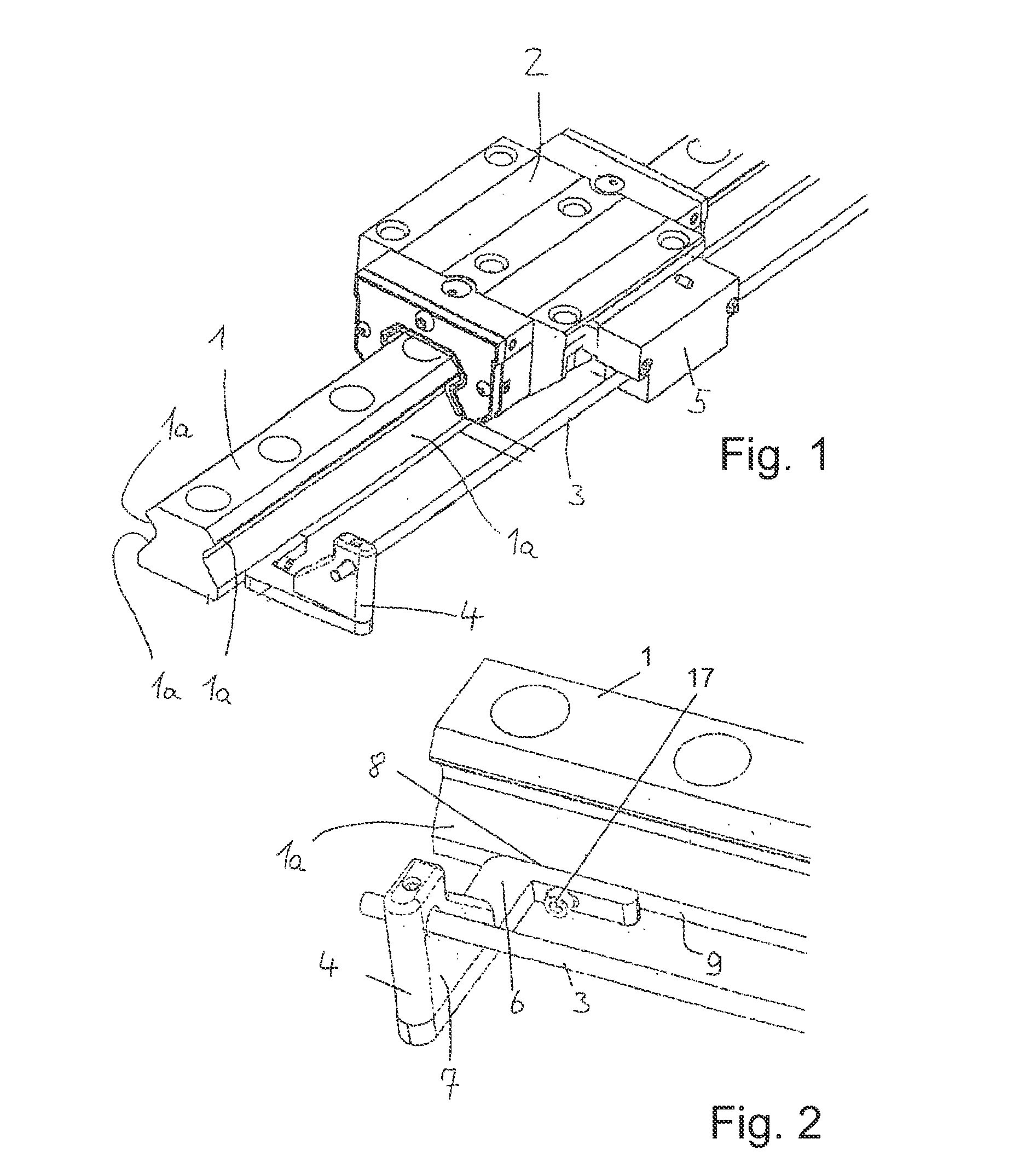
[0021]FIG. 2 shows an enlargement of a detail from FIG. 1, in which, in particular, the holder 4 can be seen clearly. The holder 4 has a holding arm 6, the lower part of which is angled. A retainer 7 is placed onto the holding arm 6 and carries the material measure 3. The retainer 7 may also be formed in one piece with the holding arm 6. The holder 4 is d...


PUM


Abstract

A guide rail of a linear guide, on guide surfaces on which a guide carriage is longitudinally displaceable. A material measure is arranged at a distance, preferably in parallel, to the guide rail and is fastened to the guide rail by means of a mount. The guide rail has a groove or a hole arranged outside the guide surface. The mount can be detachably fastened by means of expanding elements that engage with the groove or into the hole.

Description

[0001]This application is a 371 of PCT / EP2007 / 063793 filed Dec. 12, 2007, which in turn claims the priority of DE 10 2007 003 647.9 filed Jan. 25, 2007, and DE 10 2007 009 461.4 filed Feb. 27, 2007 the priority of these applications is hereby claimed and these applications are incorporated by reference herein.FIELD OF THE INVENTION[0002]The present invention relates to a guide rail of a linear guide, on the guide surfaces of which a guide carriage can be mounted so as to be longitudinally displaceable.BACKGROUND OF THE INVENTION[0003]Linear guides are often provided with a length measuring device so that a guide carriage guided longitudinally displaceably on the guide rail can be positioned satisfactorily by suitable drive and control means. DE 102 14 426 A1, for example, discloses a guide rail. The material measure arranged laterally next to the guide rail is held on the guide rail via a holder. The holder provides two approximately u-shaped brackets which are fastened in each case...

Claims


Application Information

Patent Timeline
IPC IPC(8): F16C29/02G01B21/02
CPCF16C29/005G01D11/02
Inventor RUDY, DIETMARMENGES, MARTINNATALE, MARIO
Owner SCHAEFFLER TECH AG & CO KG
Why Eureka
Try Eureka