
Transactional processing for clustered file systems

a file system and transaction processing technology, applied in the field of transactional processing in a clustered file system, can solve the problems of invalid intermediate state of the file system, unanswered in existing file system, and generally not supporting the requirements of existing file system

Inactive Publication Date: 2012-09-25
INT BUSINESS MASCH CORP
View PDF9 Cites 24 Cited by
  • Summary
  • Abstract
  • Description
  • Claims
  • Application Information

AI Technical Summary

Benefits of technology

[0011]providing a local cache memory on each node to reduce file system access to the shared storage and for processing modifications to the file system data;

Problems solved by technology

Existing file systems generally do not support these requirements.
Occurrence of faults (like a power failure or a system unrecoverable fault) during processing of these internal operations can leave the file system in an invalid intermediate state.
However, the requirement of considering several user operations, defined and grouped by the user logic, as a single atomic transaction, and the subsequent requirements facilitating transaction processing of user oriented operations, remain unanswered in existing file systems.
Note that in non-journaled file systems, detecting and recovering from inconsistencies due to faults during processing requires a complete scan of the file system data structures, which may take a long time.
In clustered (a.k.a. shared disk) file systems, which provide concurrent read and write access for multiple clustered computers to files stored in shared external storage devices, transaction processing and consistency should be implemented over the cluster and is more challenging.

Method used


Image

  • Transactional processing for clustered file systems
  • Transactional processing for clustered file systems
  • Transactional processing for clustered file systems

Examples


case 3 (

[0112]Case 3 (180): Agent A 182 sends a request 184 that reaches agent B 186 after B sends a request 196 on the same data segment. Both requests 184, 196 become blocked on the remote side as their handling procedures identify an ongoing messaging session. One of the two users that triggered sending the requests times out and the agent of the timed out user eventually processes the request of its counterpart agent and sends a response. Assume without loss of generality that the user timing out 190 is affiliated with agent A, the response 198 reaches the user affiliated with agent B before timing out 199, in which case only agent B becomes the owner 194, since agent A shall discard 197 the response 188 to the original request 184 of agent A.

case 4 (

[0113]Case 4 (200): This case is similar to case 3, except that the response 218 from agent A 202 reaches the user affiliated with agent B 206 after timing out 219, in which case both responses 218, 208 sent by both agents are discarded 215, 217 by their remote agents. Therefore both agents are not the owners 212, 214 of the data segment.

A-6. Resolving a No Owner Messaging Deadlock

[0114]In the scenario of case 4, both agents 202, 206 send concurrent permission requests 204, 216 on a same data segment not owned by both, and both responses 208, 218 are discarded 217, 215, thus failing both requests and failing to recover ownership of that data segment 212, 214. This scenario is referred to as a no owner messaging deadlock. Data segments that are accessed with high contention from both agents, for which ownership is lost, may exhibit sequentially repeating occurrences of this scenario, thus detrimentally affecting performance. To improve performance the DSM algorithm of the present emb...


PUM


Abstract

Systems and methods for transactional processing within a clustered file system wherein user defined transactions operate on data segments of the file system data. The users are provided within an interface for using a transactional mechanism, namely services for opening, writing and rolling-back transactions. A distributed shared memory technology is utilized to facilitate efficient and coherent cache management within the clustered file system based on the granularity of data segments (rather than files).

Description

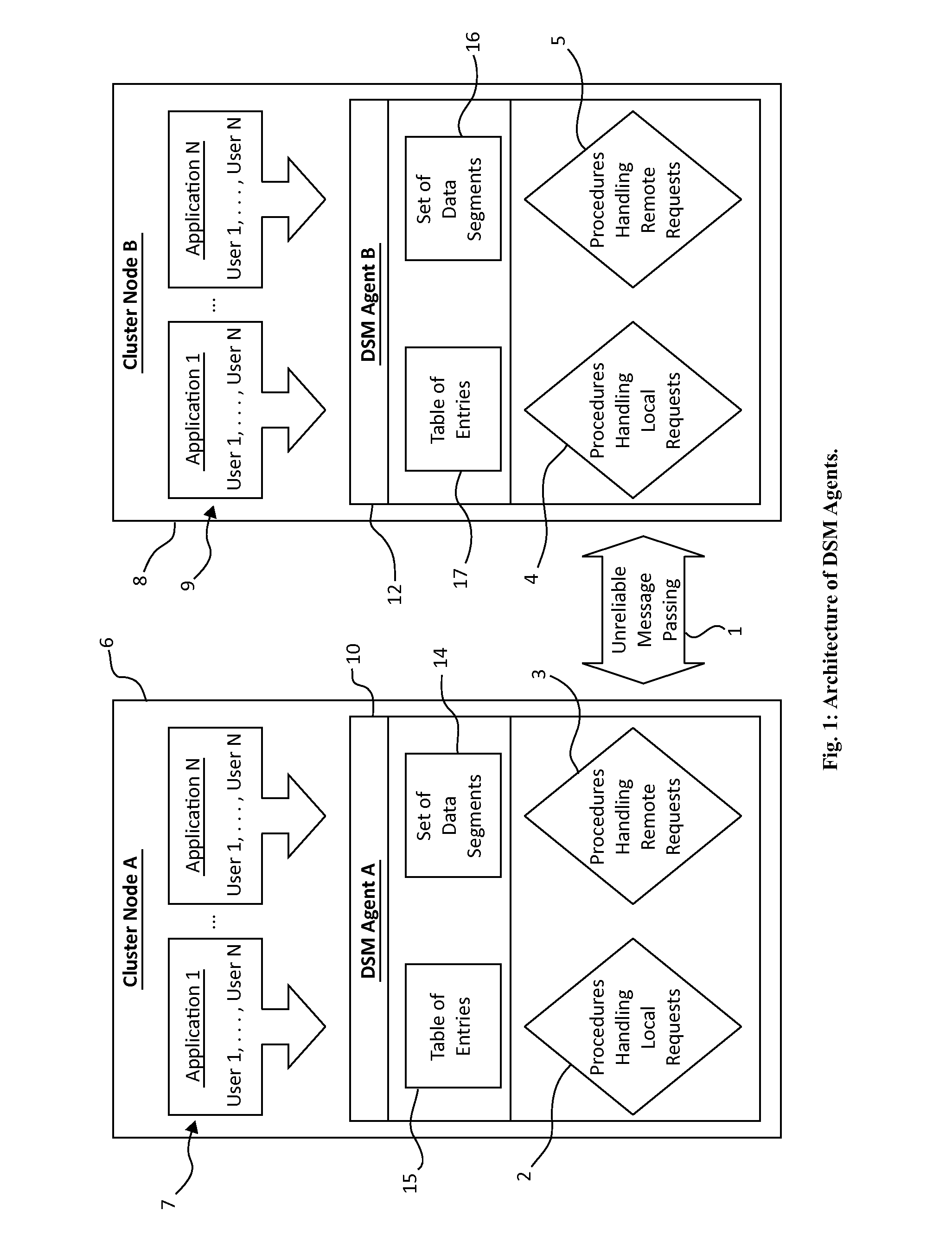
FIELD OF THE INVENTION[0001]The present invention relates to apparatus and methods for implementing transactional processing in a clustered file system, implemented over a cluster of connected computers.BACKGROUND[0002]Distributed shared memory (DSM) provides an abstraction that allows users to view a physically distributed memory of a distributed system as a virtual shared address space. DSM provides a convenience for programmers of distributed applications, reducing or eliminating the requirement to be aware of the distributed architecture of the system and the requirement to use a less intuitive form of communication on a distributed system via message passing. DSM also provides a means to directly port software written for non-distributed systems to work on distributed systems.[0003]There are many forms of DSM algorithms and technologies, all of them sharing a fundamental architecture of being composed of distributed agents deployed on a plurality of clustered nodes, maintaining...

Claims


Application Information

Patent Timeline
Patent Type & Authority Patents(United States)
IPC IPC(8): G06F17/40
CPCG06F17/30115G06F17/3007G06F17/30132G06F17/30227G06F17/30203G06F12/0828G06F12/084G06F17/30091G06F17/30194G06F21/6218G06F12/0815G06F16/13G06F16/172G06F16/182G06F16/183G06F16/1865G06F16/24552G06F16/11G06F16/16G06F12/0802G06F2212/604
Inventor ARONOVICH, LIORTOAFF, YAIRPAZ, GILASHER, RON
Owner INT BUSINESS MASCH CORP
Learn More