Rotation mechanism for laser emitter

a laser emitter and rotating mechanism technology, which is applied in the direction of instruments, furniture parts, machine supports, etc., can solve the problems of difficult adjustment, difficult adjustment, and difficult adjustment, etc., and achieve the effect of compact arrangement of the rotating mechanism, complex setting, and easy adjustmen

Inactive Publication Date: 2012-09-25
TJM DESIGN CORP
View PDF13 Cites 3 Cited by
  • Summary
  • Abstract
  • Description
  • Claims
  • Application Information

AI Technical Summary

Benefits of technology

[0017]The rotation mechanism for a laser emitter according to the present invention has a layered structure wherein the laser emitter is directly connected to the uppermost rotary ring in the form of a manual coarse rotation ring, and the automatic coarse rotation ring and the automatic fine rotation rings are arranged below the manual coarse rotation ring. Therefore, a manual operating force is applied only to the manual rotation rings, without being influenced by the weight of the driving system or electric power supply. In other words, the manual rotation can be performed lightly, without applying any load that may cause failure of the automatic rotation rings.
[0018]According to the present invention, furthermore, since the driving means for the automatic rotation rings are each arranged on the relevant rotation ring on the lower side, the provision of a dedicated space for the driving means is unnecessary, thereby readily realizing a compact arrangement of the rotation mechanism.
[0019]In practical application, the laser emitter should be rotated at a high speed when the laser line is situated remote from the position to be marked, whereas the laser emitter should be rotated at a low speed when the laser line is situated close to the position to be marked. However, when the driving means comprises a DC motor which is suitable for a high speed rotation, as a general matter, it is not easy to precisely stop the DC motor at a predetermined angular position. Thus, the rotation speed of the DC motor must be controlled by adjusting the PWM signal, for example, thereby requiring a complex setting and complicated structure. In contrast, when a stepping motor is used, in order to precisely stop the motor at the position to be marked, it would be inevitable to minimize the amount of angular rotation of the motor per unit step. However, when the stepping motor is rotated with a minimized amount of angular rotation, there arises a disadvantageous problem that a longer time is required to complete the positioning of the laser line. When, as in a preferred embodiment of the present invention, a DC motor and a stepping motor are used in combination, a precise positioning of the laser line at the position to be marked can be performed within a short time, by the DC motor for the coarse adjustment and the stepping motor for the stepping motor.
[0020]When the laser line is positioned to the center (i.e., the convergent point) of the light receiving sensor of the receiver by driving the automatic fine rotation ring by means of the stepping motor, because the stepping motor drives the automatic fine rotation ring in a stepwise manner with a predetermined stepping angle, there may be instances wherein the laser line passes over the convergent point. In such a case, because the laser line is continuously rotated in a direction away from the convergent point, the positioning cannot be performed quickly. Such a potential problem can be eliminated by a preferred embodiment of the present invention, wherein power transmission means is arranged between the automatic fine rotation ring and the driving means thereof, and provided with interrupters which performs a recovery control by detecting the sliding limits of a guide member for controlling the rotation of the automatic fine rotation ring and causing, when it has been detected that the sliding limit has been reached, the automatic fine rotation ring and the automatic coarse rotation ring to be repeatedly rotated in a clockwise or counterclockwise manner whenever necessary, so as to position the laser line with a convergent point.

Problems solved by technology

This type of laser emitter requires an extremely delicate and precise adjustment when the laser line is to be manually focused to the target site by an operator, in particular when the laser line is generated so as to form a vertical line.
Such an adjustment is a heavy burden to the operator.
It is needless to say that the adjustment becomes less easy when the distance between the laser emitter and the light receiving element increases, even when a fine adjustment mechanism is provided.
While the laser emitter of remote control type as mentioned above allows simplification of the manual operation and proved to be an effective measure for reducing the time required for marking, there is such disadvantage that the system becomes large due to the requirement for a driving source for the laser emitter.
Besides, while a coarse positioning adjustment is generally performed by manually rotating the emitter main body, particularly in the case of the laser emitter of remote control type, the driving system tends to be subjected to an excessive load when the emitter main body is manually rotated, which may cause mechanical failures.

Method used


Image

  • Rotation mechanism for laser emitter
  • Rotation mechanism for laser emitter
  • Rotation mechanism for laser emitter

Examples


Embodiment Construction

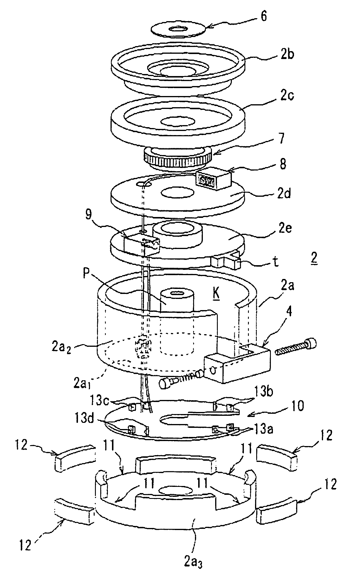
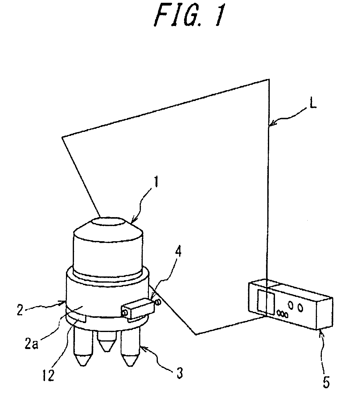
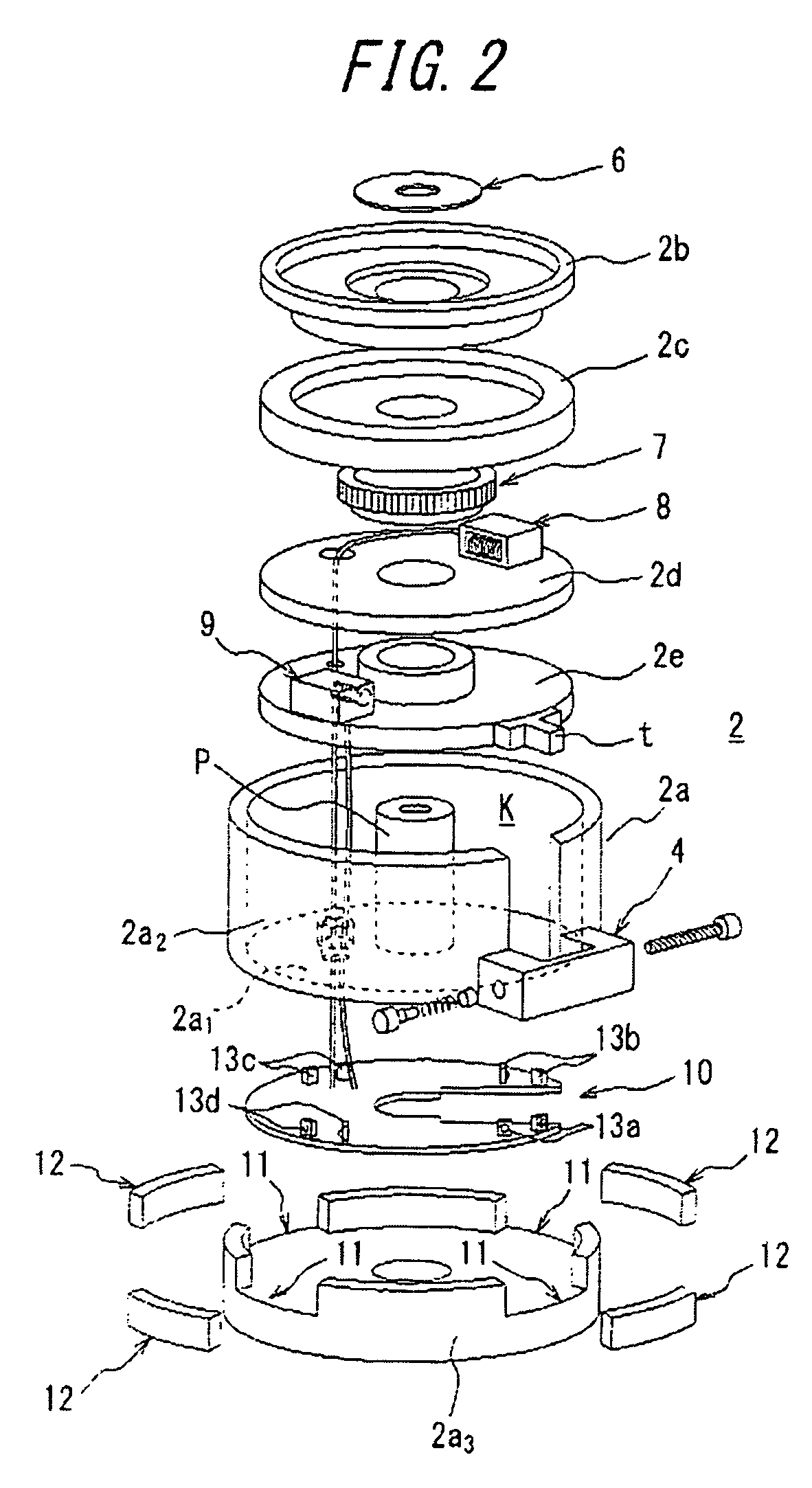
[0035]With reference to FIG. 1, there is shown the arrangement of an automatic tracking-type laser emitter and a receiver for receiving a laser line (e.g., a vertical line, as in the illustrated embodiment) which is generated by the emitter, wherein the laser emitter is equipped with the rotation mechanism according to the present invention. The exploded perspective view of the rotation mechanism is shown in FIG. 2.

[0036]In the drawings, reference numeral 1 denotes the laser emitter, reference numeral 2 denotes a rotation mechanism for rotatably supporting the laser emitter 1, reference numeral 3 denotes a tripod provided at the bottom portion of a casing 2a of the rotation mechanism 2, reference numeral 4 denotes a knob portion for causing a coarse rotation of a manual coarse rotation ring of the rotation mechanism, and reference numeral 5 denotes a receiver (light receiving unit) for receiving the laser generated by the laser emitter 1.

[0037]The casing 2a of the rotation mechanism...


PUM


Abstract

A rotation mechanism for mounting and rotatably supporting a laser emitter thereon includes a casing including a bottom wall and a side wall connected to the bottom wall, said casing defining therein a receiving space. A plurality of rotation rings are arranged as being layered with each other in the receiving space of the casing. The rotation rings include an uppermost rotation ring in the form of a manual coarse rotation ring that is directly connected to the laser emitter so as to support the laser emitter, for manually rotating the laser emitter to achieve a coarse angular positioning thereof, an automatic coarse rotation ring for rotating the laser emitter at a relatively high speed together with the rotation ring thereon, a manual fine rotation ring for slightly rotating the laser emitter manually together with the rotation ring thereon, and an automatic fine rotation ring for rotating the laser emitter at a relatively low speed, together with the rotation ring thereon. The automatic rotation rings are each provided with a driving means that is arranged on the rotation ring immediately below the relevant rotation ring.

Description

TECHNICAL FIELD[0001]The present invention relates to a rotation mechanism for a laser emitter, which can be suitably used for marking purpose in construction or civil engineering sites, and which is designed to rapidly and accurately rotate the laser emitter to a position corresponding to the direction in which laser is to be emitted.BACKGROUND ART[0002]There is known a laser emitter for emitting and displaying a laser line on a surface of a wall, ceiling or floor, which includes a rotation mechanism incorporated into the lower end region of the emitter main body, such that the laser line generated can be radiated over an angular range of 360°. In this instance, when the laser emitter has been installed, the marking is performed after manually operating the rotation mechanism so as to cause a coarse rotation of the emitter main body, by accurately aligning the laser line to the target site by a fine adjusting movement (cf. Patent Document 1: JP9-166436A).[0003]This type of laser em...

Claims


Application Information

Patent Timeline
Patent Type & Authority Patents(United States)
IPC IPC(8): A47B91/00
CPCG01C15/004G01C15/00
Inventor SATO, KAZUOIWASAKI, WATARUMANO, KOICHIRO
Owner TJM DESIGN CORP
Why Eureka
Try Eureka