Navigation, identification, and collision avoidance antenna systems
a technology of collision avoidance and navigation, applied in the field of aircraft antennas, can solve the problems of dme, transponder and tcas systems, which place demanding performance requirements on antenna structures
- Summary
- Abstract
- Description
- Claims
- Application Information
AI Technical Summary
Benefits of technology
Problems solved by technology
Method used
Image

Examples
embodiment 40
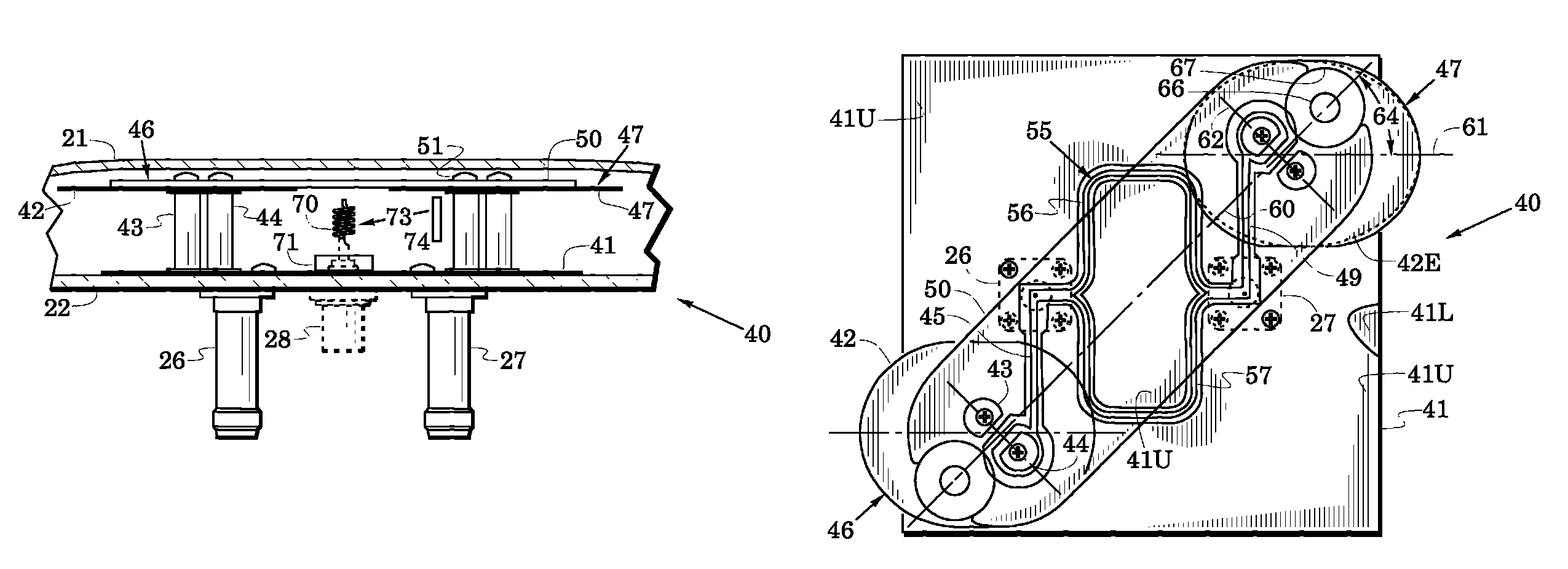
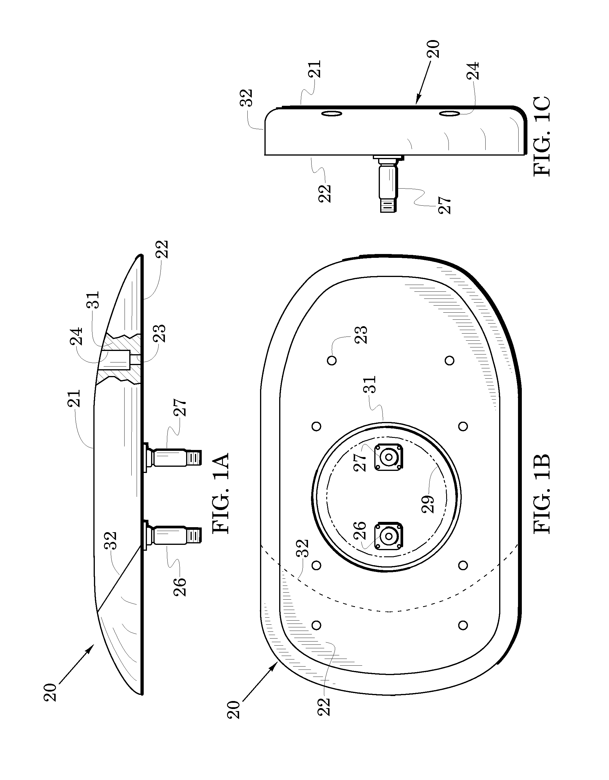
[0026]FIG. 2A is an enlarged view of FIG. 1A with a side of the radome 21 removed to expose an antenna embodiment 40 within. FIG. 2B is a top view of the antenna 40 of FIG. 2A with the radome removed to expose the antenna. These figures include elements of FIGS. 1A-1C with like elements indicated by like reference numbers. Although these antenna structures can be sized to operate at various frequency bands, they are sized in an exemplary embodiment to operate over a frequency band bounded by the frequencies of 960 MHz and 1220 MHz.
[0027]FIGS. 2A and 2B show a conductive ground plane 41 that is carried on the baseplate 22. A top load 42 is spaced from the ground plane by a shorted post 43 and a feed post 44 is spaced away from the shorted post. The shorted post is electrically grounded to the ground plane and the feed post is electrically joined to a transmission line 45 that leads to the center conductor of the connector 26.
[0028]The transmission line is preferably formed by a signa...
embodiment 74
[0036]In the illustrated embodiment, the probe 70 is formed as a coil but various other embodiments may be used. For example, the substitution arrow 73 shows that a rod embodiment 74 may be substituted for the coil. Detected signals of the probe 70 may be conditioned through electronics 71 (e.g., a detector and a limiter) to provide a scaled DC signal which exits the antenna through a circuit path to a selected connector. The selected connector may be the connector 26, the connector 27 or a connector 28 (shown in broken lines) that is added in FIG. 2A between the connectors 26 and 27.
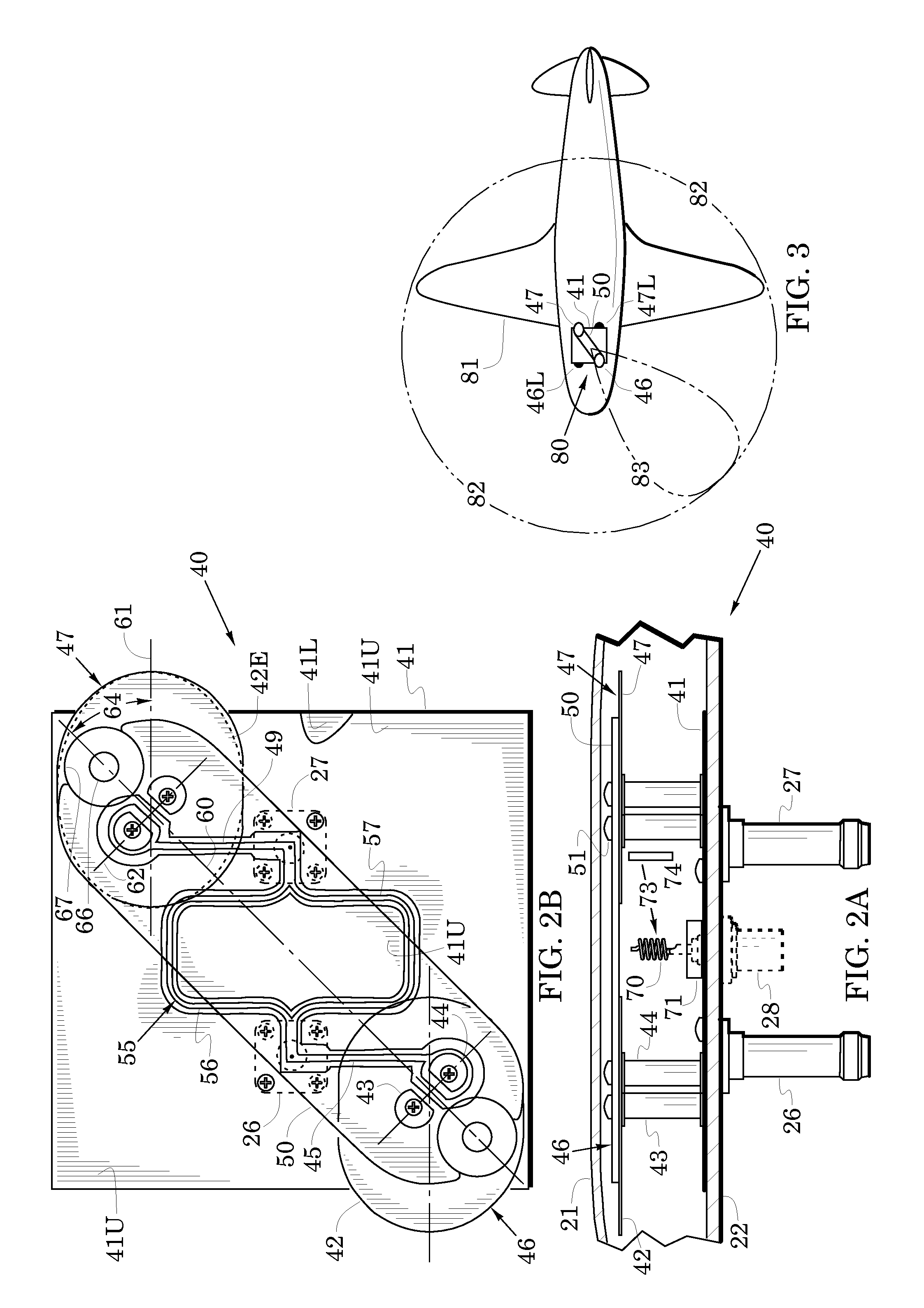
[0037]FIG. 3 illustrates an antenna system 80 that is formed by installing a first one of the antenna 40 of FIGS. 2A and 2B on the upper skin of the airplane and by inverting a second one of the antenna 40 and installing it on the lower skin of the airplane. The first and second monopoles 46 and 47 of the first antenna are shown in white along with their associated support bar 50. To enhance illustratio...
embodiment 110
[0042]A probe 70 was shown in FIGS. 2A and 2B. As described above, the probe provided a signal indicative of the phase of signals associated with the monopoles 46 and 47. This signal can be useful, for example, to a TCAS processor for calibrating the antenna to the remainder of the TCAS system. FIG. 7 illustrates other structure which is useful for calibrating an antenna. In particular, FIG. 7 shows an antenna embodiment 110 which includes elements of the antenna 40 of FIGS. 2A and 2B with like elements indicated by like reference numbers. This embodiment provides a synthesizer 112 which can provide phase-stable signals to a selected one of the coaxial connectors 26 and 27 through a circuit path that is indicated by a heavy broken line in FIG. 7. The frequency of the signals of the synthesizer 112 can be commanded via a command line and power may be provided to the synthesizer via a power line. These circuit lines 113 may lead, for example, to a multi-pin embodiment of the connector...
PUM
 Abstract
Description
Claims
Application Information
 - R&D
- Intellectual Property
- Life Sciences
- Materials
- Tech Scout
- Unparalleled Data Quality
- Higher Quality Content
- 60% Fewer Hallucinations
Browse by: Latest US Patents, China's latest patents, Technical Efficacy Thesaurus, Application Domain, Technology Topic, Popular Technical Reports.
© 2025 PatSnap. All rights reserved.Legal|Privacy policy|Modern Slavery Act Transparency Statement|Sitemap|About US| Contact US: help@patsnap.com