
Sub-network load management for use in recharging vehicles equipped with electrically powered propulsion systems

a technology of electrically powered propulsion system and sub-network load management, which is applied in the direction of charging stations, electric vehicle charging technology, transportation and packaging, etc., to achieve the effect of enhancing the operation of the e-grid sub-network load manager

Inactive Publication Date: 2012-09-04
LAVA FOUR
View PDF11 Cites 239 Cited by
  • Summary
  • Abstract
  • Description
  • Claims
  • Application Information

AI Technical Summary

Benefits of technology

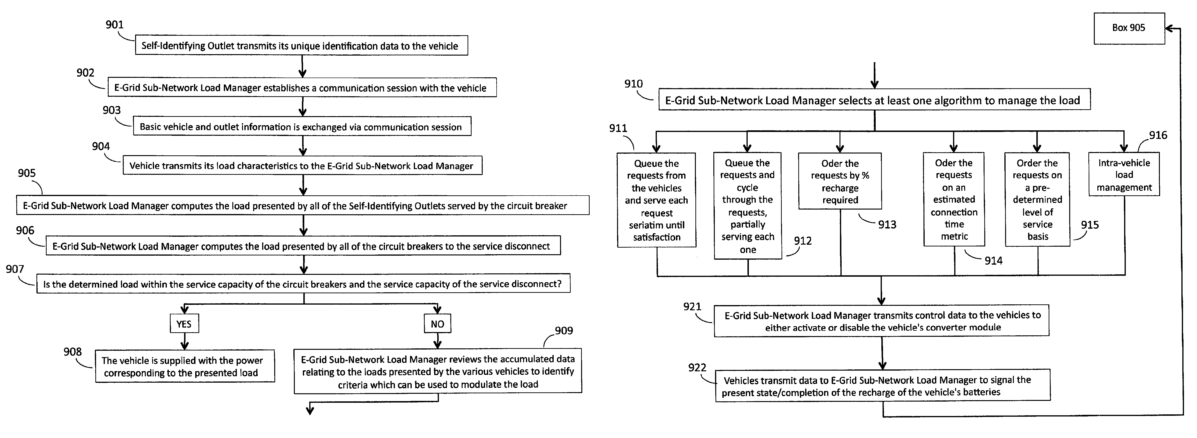
[0028]The implementation of the E-Grid Sub-Network Load Manager can include intelligent Self-Identifying Power Sources which can be controlled to deliver power on a basis determined by the E-Grid Sub-Network Load Manager and / or the use of intelligent Self-Metering Vehicles which can be controlled to request power on a basis determined by the E-Grid Sub-Network Load Manager or combinations of both. In addition, the availability of information from the Self-Metering Vehicles relating to power required to recharge, recharge current handling capacity, estimated time of connection, and class of service for which the vehicle owner has contracted all enhance the operation of the E-Grid Sub-Network Load Manager.

Problems solved by technology

It is a problem in the field of recharging systems for vehicles equipped with electrically powered propulsion systems to bill the vehicle operator for the energy consumption where the Electric Grid is used as the source of power to charge the vehicular battery banks.
Recharging a vehicle which is equipped with an electrically powered propulsion system results in the premises owner errantly being billed for the recharging and the vehicle owner not being billed at all.
Not only is this system very expensive to implement, but it remains highly centralized and is certainly not ubiquitous.
This example solution and other analogous grid-centric solutions are not possible without an incredible capital expenditure for new infrastructure and an extensive build time to provide widespread recharging capability.
Thus, the problems with centralized vehicular charging are:infrastructure cost,lack of ubiquity in the infrastructure's extent,extensive time to deploy a nationwide system,can't manage / control access to electricity without a per outlet meter,no ubiquity of billing for downloaded electricity,no method to assure a given utility is properly paid,no method to provide revenue sharing business models,no methods to manage and prevent fraud,incapable of instantaneous load management during peak loads,incapable of load management on a block by block, sector by sector load, or city-wide basis, andincapable of billing the energy “downloaded” to a given vehicle, where a given vehicle is random in its extent, and where the vehicle is plugged into the grid is also random in its extent.
When a cellular subscriber “roamed” out of their home “network”, they couldn't make phone calls, or making phone calls was either extremely cumbersome or expensive or both.
One problem faced by the E-Grid is that typically a number of vehicles arrive at a destination in close temporal proximity, connect to the power sources served by a service disconnect, and concurrently request service.
This is a peak load issue, where the existing service disconnect is unable to manage a plurality of concurrently received requests for service and, therefore, is limited in the number of vehicles that can be served.

Method used


Image

  • Sub-network load management for use in recharging vehicles equipped with electrically powered propulsion systems
  • Sub-network load management for use in recharging vehicles equipped with electrically powered propulsion systems
  • Sub-network load management for use in recharging vehicles equipped with electrically powered propulsion systems

Examples


utility embodiment

Multi-Utility Embodiment

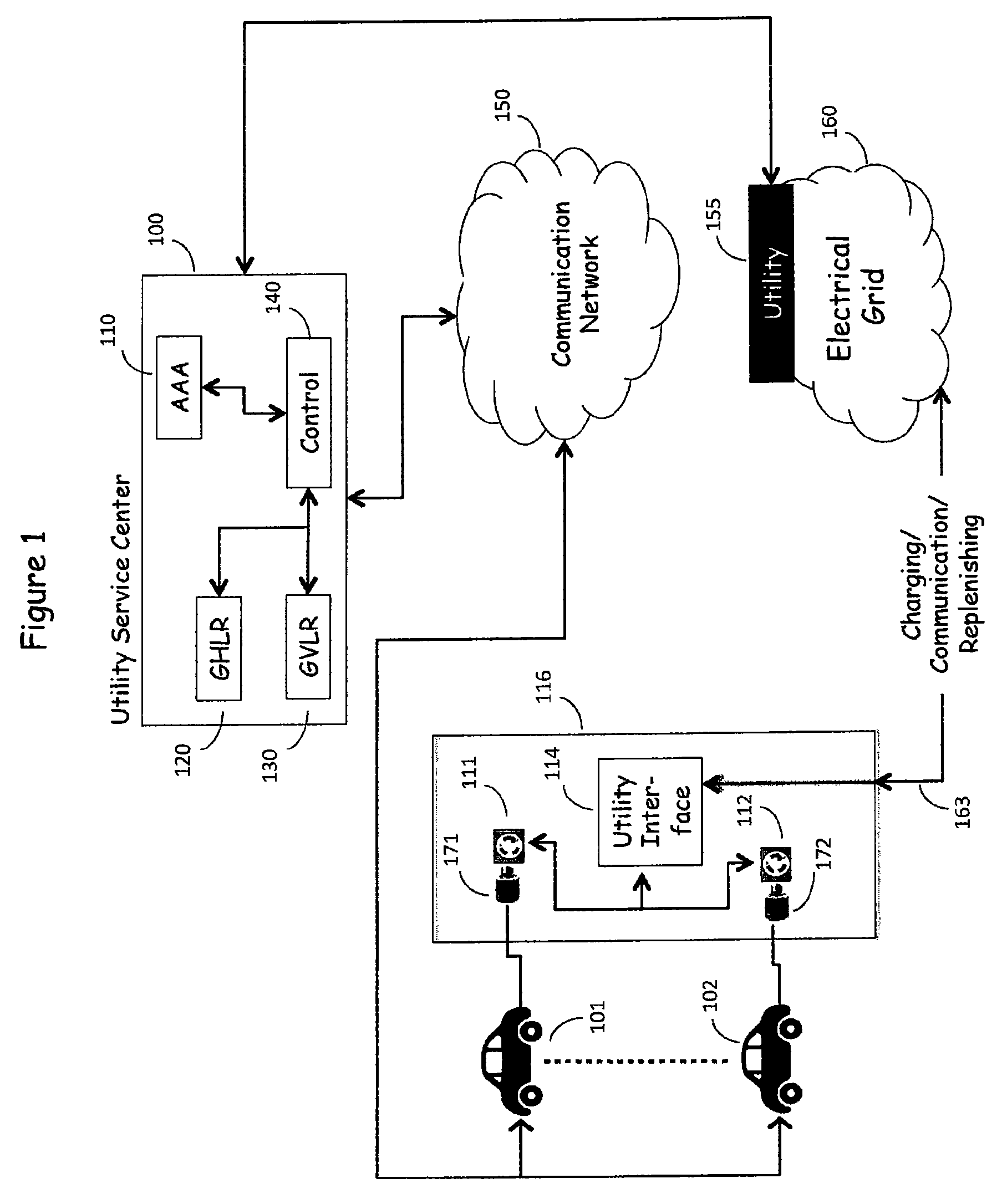
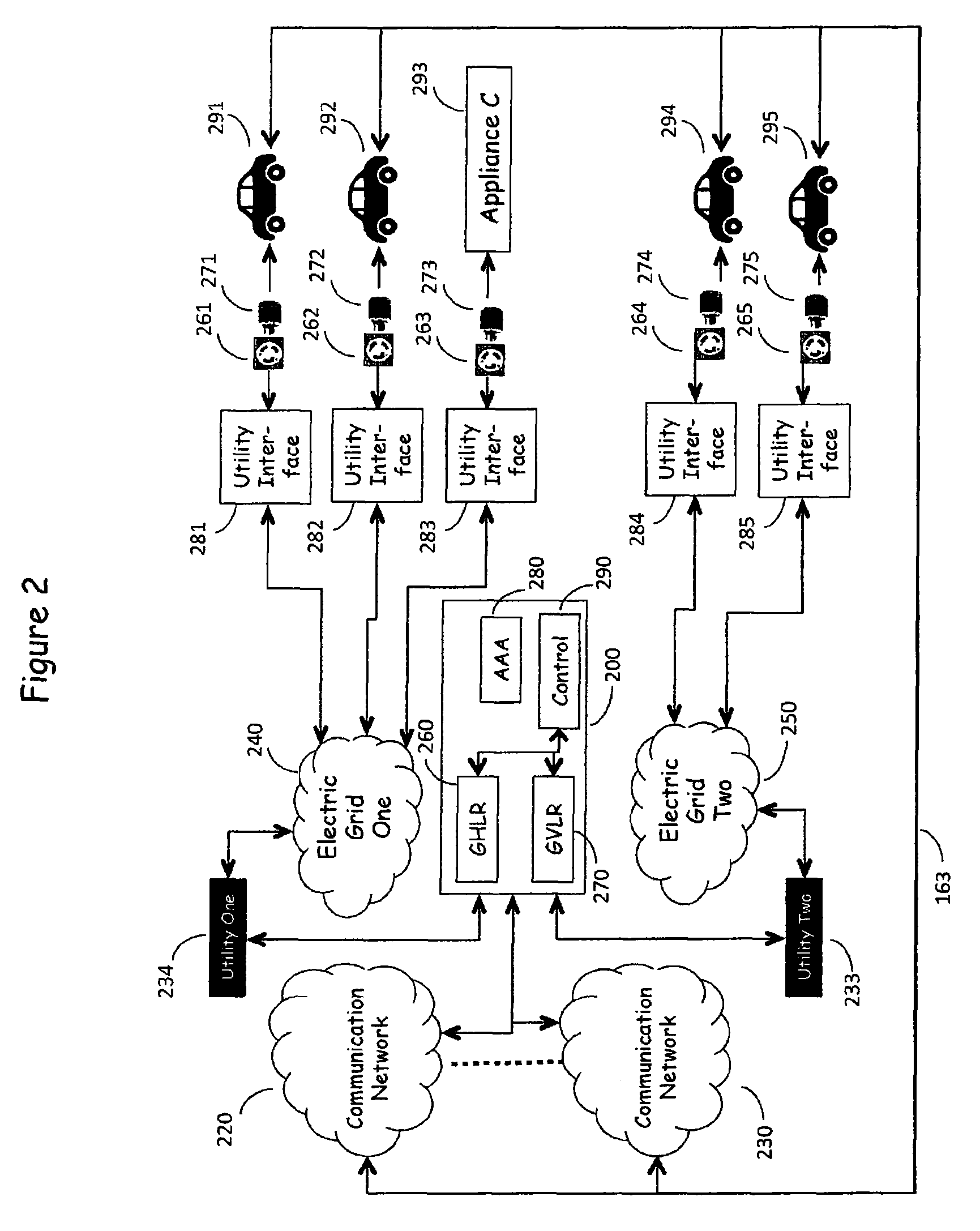
[0045]FIG. 1 is, in reality, a multidimensional network in which N electric utilities are served by M Electric Grids with corresponding communication networks, as shown in FIG. 2.

[0046]Electric Grids 240, 250 shown in FIG. 2 represent the source of electric power, as provided by multiple utility companies which serve a wide geographic area and provide electric power to a multitude of customers via utility interfaces 281-285. The utility interfaces 281-285 serve to measure the energy consumption by the various outlet connected loads, such as Vehicles 291-295. These elements represent the existing, present day electric power delivery infrastructure as described above. Electric power traditionally flows from the Electric Grid 240, 250 to the utility interfaces 281-285 and thence to the customer's loads—Vehicles 291-295 via plug 271-275-outlet 261-265 combinations, but power also can flow in the reverse direction, from the vehicular battery banks of Vehicles 291-...


PUM


Abstract

The E-Grid Sub-Network Load Manager operates to regulate the demands presented by the vehicles to the associated Sub-Network thereby to spread the load presented to the service disconnect over time to enable the controllable charging of a large number of vehicles. The load management can be implemented by a number of methodologies, including: queuing requests and serving each request in sequence until satisfaction; queuing requests and cycling through the requests, partially serving each request, then proceeding to the next until the cyclic partial charging service has satisfied all requests; ordering requests pursuant to a percentage of recharge required measurement; ordering requests on an estimated connection time metric; ordering requests on a predetermined level of service basis; and the like. It is evident that a number of these methods can be concurrently employed thereby to serve all of the vehicles in the most efficient manner that can be determined.

Description

CROSS-REFERENCE TO RELATED APPLICATIONS[0001]This Application is a continuation-in-part of U.S. application Ser. No. 12 / 329,349 tided “Self-Identifying Power Source For Use In Recharging Vehicles Equipped With Electrically Powered Propulsion Systems” filed 5 Dec. 2008 now abandoned, and U.S. application Ser. No. 12 / 329,368 titled “System For On-Board Metering Of Recharging Energy Consumption In Vehicles Equipped With Electrically Powered Propulsion Systems” filed 5 Dec. 2008 now abandoned, and U.S. application Ser. No. 12 / 329,389 titled “Network For Authentication, Authorization, And Accounting Of Recharging Processes For Vehicles Equipped With Electrically Powered Propulsion Systems” filed 5 Dec. 2008 now abandoned. In addition, this Application is related to a US Application titled “Intra-Vehicle Charging System For Use In Recharging Vehicles Equipped With Electrically Powered Propulsion Systems”, US Application titled “Dynamic Load Management For Use In Recharging Vehicles Equipp...

Claims


Application Information

Patent Timeline
Patent Type & Authority Patents(United States)
IPC IPC(8): H02J7/14H02J7/00
CPCB60L11/1816B60L11/1842B60L11/1846B60L11/1848B60L11/185B60L11/1824Y02E60/721B60L2260/44Y02T10/7005Y02T90/121Y02T90/128Y02T90/14Y02T90/169Y04S10/126Y04S30/14Y02T10/7072B60L55/00B60L53/65B60L53/665B60L53/11B60L53/18Y02E60/00Y02T10/70Y02T90/12Y02T90/167
Inventor TYLER, RICHARD M.MCKENNA, DANIEL B.GRAZIANO, JAMES M.
Owner LAVA FOUR
Learn More