Eureka AIR delivers breakthrough ideas for toughest innovation challenges, trusted by R&D personnel around the world.

Ocular motor controller using principle of vestibulo-ocular reflex

a technology of ocular motor and vestibulo-ocular reflex, which is applied in the field of ocular motor controller, can solve the problems of image blurring and blurring, and achieve the effects of preventing image blurring, high speed, and simplifying the correction mechanism of ocular motor

Active Publication Date: 2012-08-28
ANHUI EYEVOLUTION TECH CO LTD
View PDF5 Cites 8 Cited by
  • Summary
  • Abstract
  • Description
  • Claims
  • Application Information

AI Technical Summary

Benefits of technology

[0018]According to the ocular motor controller of the present invention using the principle of vestibulo-ocular reflex, the image blurring can be prevented at high speed. Further, by simplifying the correction mechanism of the ocular motor as needed from the physiological and anatomical point of view, it is possible to constitute the correction section by a simple analog circuit at lower cost.

Problems solved by technology

Such systems have a problem of blurring of an image picked up by the ocular device.
This is a main cause of the image blurring.

Method used


Image

  • Ocular motor controller using principle of vestibulo-ocular reflex
  • Ocular motor controller using principle of vestibulo-ocular reflex
  • Ocular motor controller using principle of vestibulo-ocular reflex

Examples


Embodiment Construction

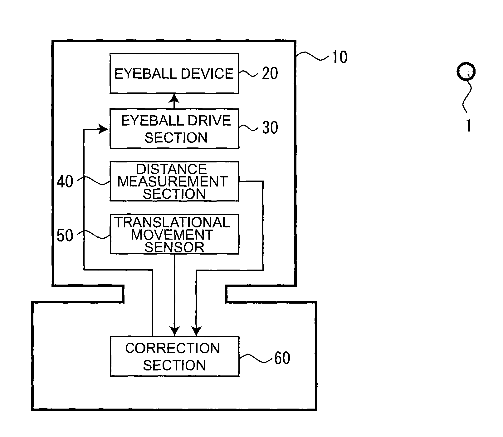
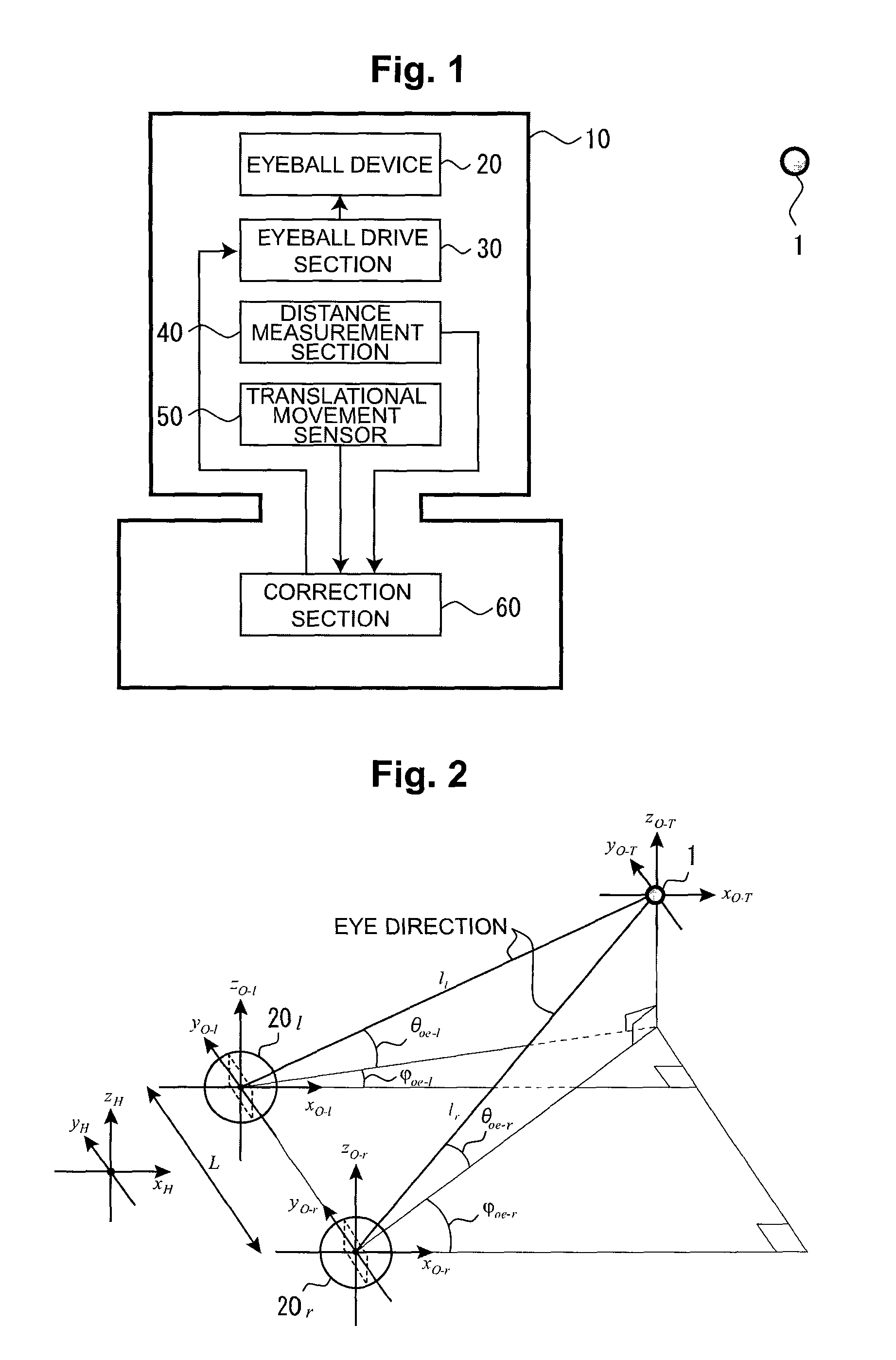
[0019]A preferred embodiment for practicing the present invention will be described below with reference to the accompanying drawings. FIG. 1 is a schematic block diagram for explaining a configuration of an ocular motor controller according to the present invention. As illustrated in FIG. 1, an ocular motor controller according to the present invention mainly includes an ocular device 20 provided in a moving object 10, an ocular drive section 30, a distance measurement section 40, a translational movement sensor 50, and a correction section 60. Although all the above components are provided in the moving object 10 in FIG. 1, the present invention is not limited to thereto. For example, the correction section 60 need not be provided in the moving object 10 but may be externally connected to the moving object 10.

[0020]Examples of the moving object 10 include various movable objects such as a vehicle and a humanoid. The ocular device 20 is mainly constituted by an image pickup device ...


PUM


Abstract

An ocular motor controller for preventing an image blur by using the principle of vestibulo-ocular reflex in response to translational movement. The ocular motor controller comprises an image pickup section (20) used as an ocular device, an ocular drive section (30) for rotating the image pickup section, a distance information acquisition section (40) for acquiring information concerning the distance from the image pickup section (20) to a visual target (1), a translational movement sensor (50) for measuring the variation due to the translational movement of a moving object, and a correction section (60) for utilizing the rotational movement driven by the ocular drive section. The correction section (60) cancels the variation due to the translational movement measured by the translational movement sensor (50) and corrects the rotation by the ocular drive section (30) by using the acquired distance information on the distance to the visual target (1) and variation information on the variation due to the translational movement so as to fix the image pickup position of the visual target (1).

Description

CROSS REFERENCE TO RELATED APPLICATION[0001]This is a 35 U.S.C. §371 application of and claims priority to International Application No. PCT / JP2008 / 001442, which was filed on Jun. 6, 2008, and which claims priority to Japanese Patent Application No. 2007-154612, which was filed on Jun. 12, 2007, and the disclosures of all the applications are incorporated herein by reference.TECHNICAL FIELD[0002]The present invention relates to an ocular motor controller provided in a moving object so as to prevent image blurring, and more particularly to an ocular motor controller that uses the principle of vestibulo-ocular reflex to prevent image blurring.BACKGROUND ART[0003]There exists various systems in which an image pickup device is provided as an ocular device in a moving object, such as an autonomous robot. Among them, high-accuracy ocular motor systems that simulate a bionic ocular motor nervous system exist. Such systems have a problem of blurring of an image picked up by the ocular devic...

Claims


Application Information

Patent Timeline
Patent Type & Authority Patents(United States)
IPC IPC(8): H04N5/228B25J19/04H04N5/225H04N5/232
CPCG03B5/00H04N5/23248H04N5/23254H04N5/23264H04N5/23258H04N23/682H04N23/6811H04N23/68H04N23/6812
Inventor ZHANG, XIAOLINODAGAWA, TSUKASAISHIHARA, LEGAL REPRESENTATIVE, YUKARI
Owner ANHUI EYEVOLUTION TECH CO LTD
Why Eureka
Eureka Blog
Learn More