
Devices, assemblies, and methods for controlling fluid flow

a technology of fluid flow and devices, applied in the direction of valve operating means/release devices, water supply installation, couplings, etc., can solve the problems of high manufacturing cost and ineffectiveness of conventional devices and assemblies for establishing medical connections

Active Publication Date: 2012-08-28
INFUSION INNOVATIONS
View PDF23 Cites 49 Cited by
  • Summary
  • Abstract
  • Description
  • Claims
  • Application Information

AI Technical Summary

Benefits of technology

"The present invention provides apparatus and methods for controlling flow through medical connectors and devices, such as IV lines and syringes. The invention offers improved safety, efficiency, and ease of use compared to conventional devices. The invention uses fewer parts, minimizes residual fluid within the connectors after disconnection, and provides visual indicators to notify the user of actuation status. The invention also utilizes rotational force to open and close fluid paths, eliminating bolus effects and providing a more desirable user experience. The invention can be used in various medical applications, such as delivering parenteral fluids and providing connectors for medical devices."

Problems solved by technology

Conventional devices and assemblies for establishing medical connections are not completely effective and are potentially unsafe.
For example, conventional medical connectors may expose the user to harmful agents during disconnection as a result of undesired bolus effects, may collect undesired fluid within their internal volumes after disconnection, may not notify the user of the actuation status during connection and disconnection, and / or may include many parts thereby making manufacture expensive.

Method used


Image

  • Devices, assemblies, and methods for controlling fluid flow
  • Devices, assemblies, and methods for controlling fluid flow
  • Devices, assemblies, and methods for controlling fluid flow

Examples


Embodiment Construction

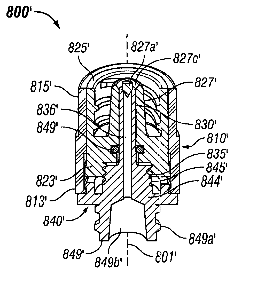
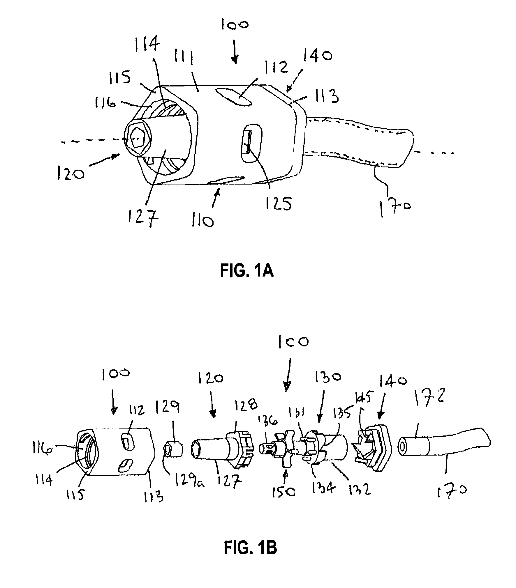
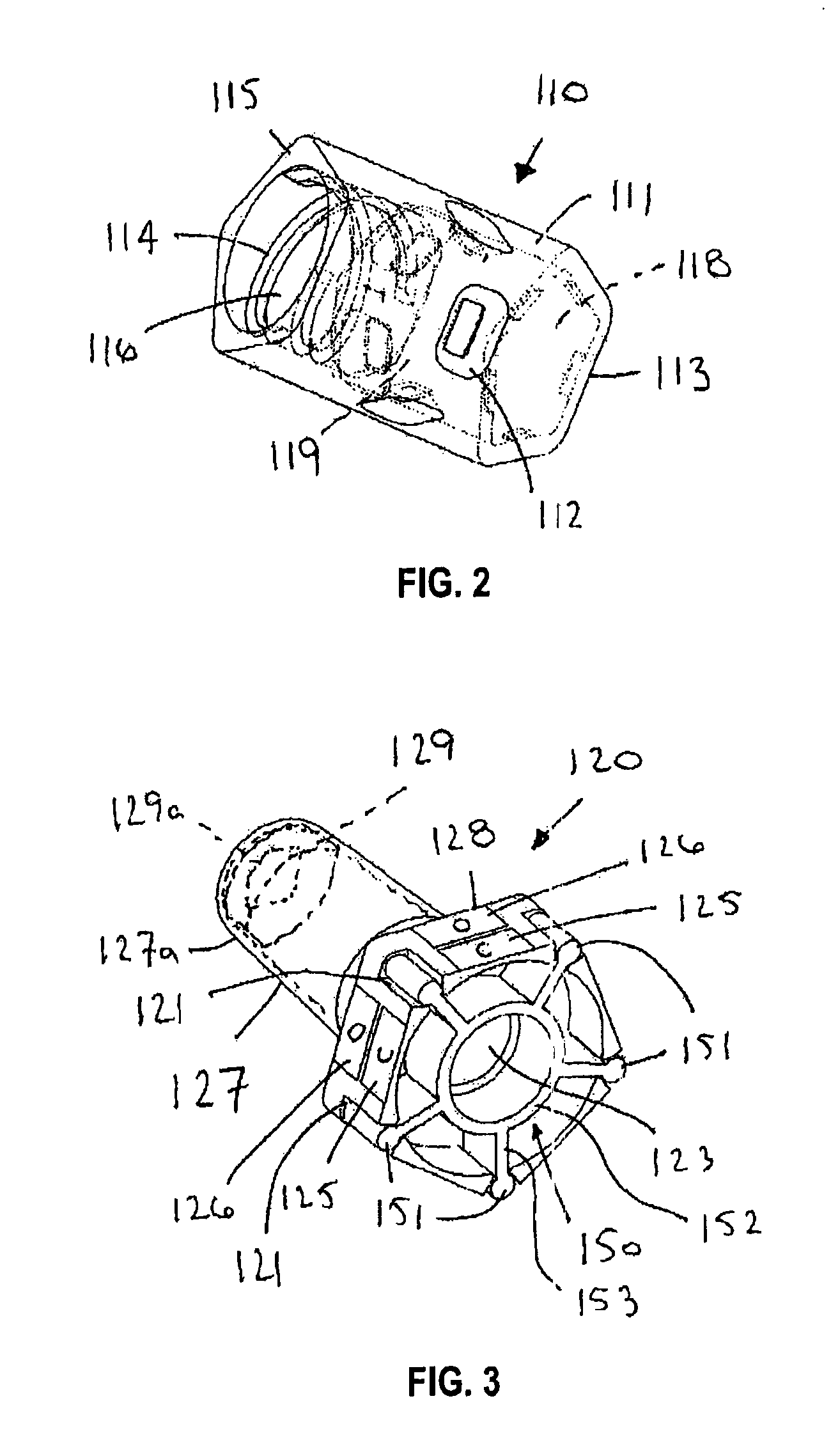
[0143]Apparatus and methods described herein may relate to valves, connecting devices, and assemblies that, among other things: utilize a rotational force for actuation to avoid or create a desired bolus effect, minimize the number of parts necessary for manufacture, decrease the internal volume of the devices and assemblies, and / or use status indicators to signify when actuation and deactuation are complete. Also, in some embodiments, the apparatus described herein may create and maintain a flat (planar) surface that is easily swabbed for cleaning and sterilization purposes. Although embodiments of valves, connecting devices, and assemblies are described herein with respect to medical connections, such valves, connecting devices, and assemblies are not limited to medical connections alone but may be applicable to any connection device or assembly that could benefit from the use of a rotational actuation force, status indicators, and / or any of the other features described herein.

[01...


PUM


Abstract

Valves are provided for controlling flow along a fluid line that includes an outer shell and an inner housing slidably disposed therein that includes connector threads surrounding a boss on one end and a passage including a tapered region within the boss. A shaft within the valve includes a base coupled to the outer shell, a tapered sealing pin disposed within the tapered region, and a fluid passage extending through the base to outlets in the sealing pin. A connector may be threaded into the one end of the inner housing, thereby slidably engaging the connector threads, camming elements on the inner housing causing the inner housing to move helically from a closed position wherein the sealing pin engages the boss to seal the outlets and an open position wherein the inner housing is directed away from the sealing pin to open a fluid path through the valve.

Description

RELATED APPLICATION DATA[0001]This application is a continuation-in-part of co-pending International Application No. PCT / US2009 / 036088, filed Mar. 4, 2009, which claims priority to U.S. provisional application Ser. No. 61 / 033,702, filed Mar. 4, 2008. This application is also related to International Application No. PCT / US2008 / 080375, filed Oct. 17, 2008, which claims priority to U.S. provisional application Ser. No. 60 / 981,233, filed Oct. 17, 2007. The entire disclosures of these applications are expressly incorporated by reference herein.FIELD OF THE INVENTION[0002]The present invention relates generally to apparatus and methods for controlling flow. More particularly, the present invention relates to devices, assemblies, and / or methods for controlling fluid flow, e.g., to connectors and / or valves for controlling flow through an IV or other fluid line into a patient, a syringe, container, and / or other medical device, and / or to systems including such connectors and / or valves.BACKGRO...

Claims


Application Information

Patent Timeline
Patent Type & Authority Patents(United States)
IPC IPC(8): F16L37/28
CPCA61M5/16881A61M39/26A61M39/10Y10T137/0318A61M2039/268
Inventor STROUP, DAVID K.
Owner INFUSION INNOVATIONS
Learn More