
Thermal holder for container

a container and container technology, applied in the field of container and container holders, can solve the problems of complex and expensive molding equipment and labor-intensive manufacturing processes, and achieve the effect of saving labor and time and improving production efficiency

Inactive Publication Date: 2012-08-28
BRECKNER JASON J
View PDF13 Cites 114 Cited by
  • Summary
  • Abstract
  • Description
  • Claims
  • Application Information

AI Technical Summary

Problems solved by technology

This is a costly and labor intensive manufacturing process that requires complex and expensive molding equipment.

Method used


Image

  • Thermal holder for container
  • Thermal holder for container
  • Thermal holder for container

Examples


Embodiment Construction

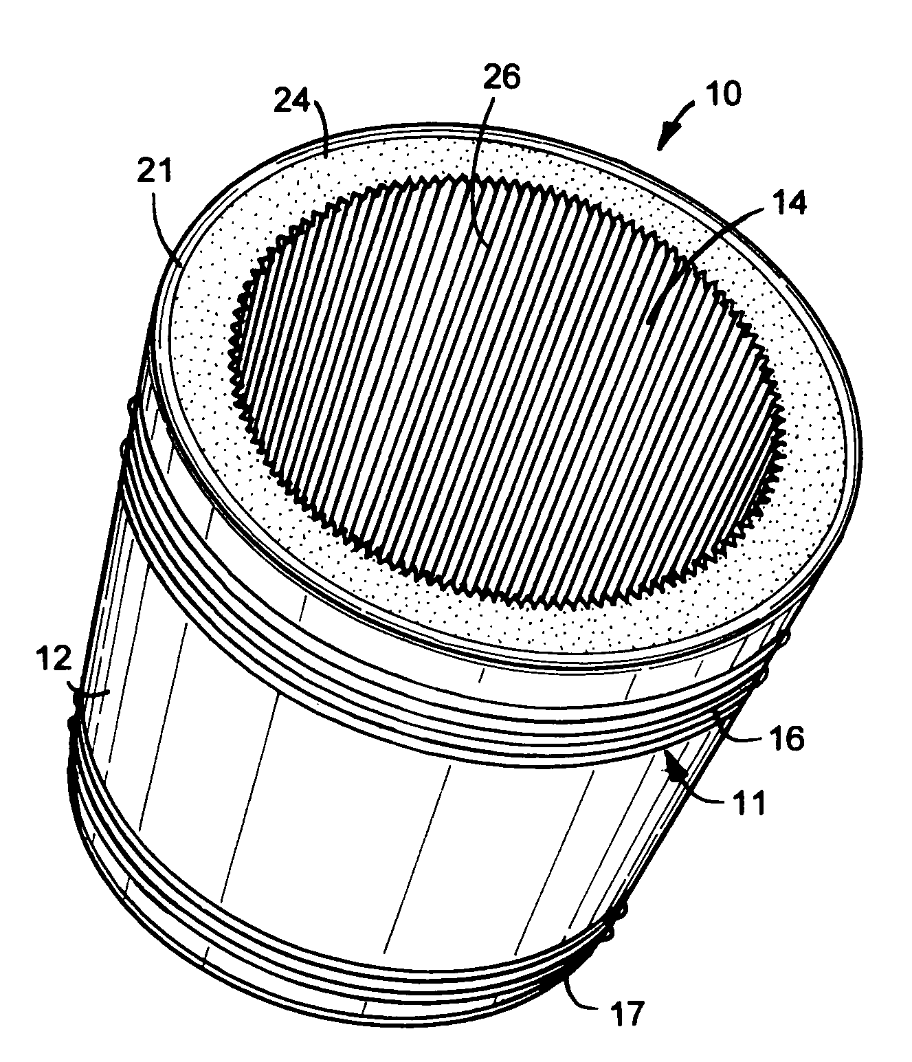
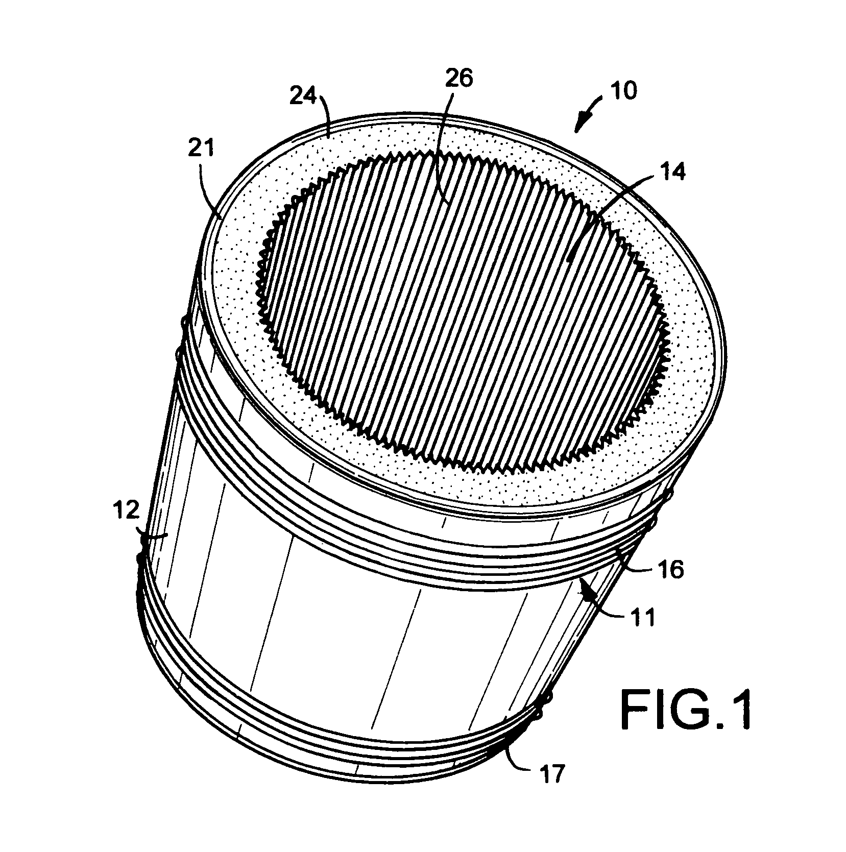
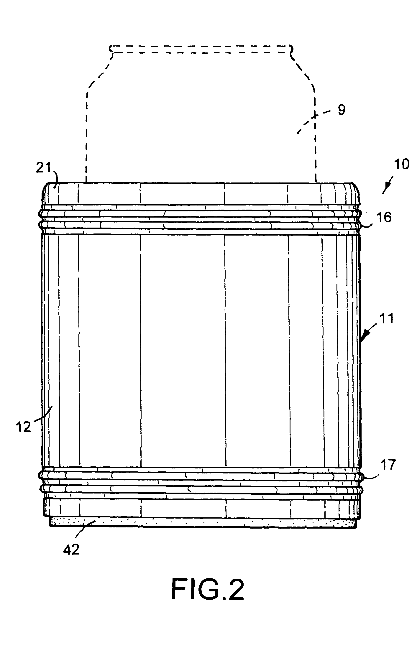
[0018]A thermal insulated holder 10 for a container 9, such as a metal can or bottle, shown in FIGS. 1 to 3, have cup-shaped cylindrical body 11 with an open top. Body 11 is a rigid stainless steel member having a cylindrical outside wall 12 and a cylindrical inside wall 13 surrounding an inside chamber 14. The upper section of wall 12 has a plurality of continuous annular ribs 16. Additional continuous annular ribs 17 are formed into the lower section of wall 12. Ribs 16 and 17 increase the strength of wall 12 and provide gripping surfaces to facilitate hand gripping of holder 10. As shown in FIG. 5, holder 10 has a circular bottom wall 18 with a center hole 19. The top end of wall 12, as shown in FIG. 6, has an inwardly turned shoulder 21. Body 11 can be a plastic or ceramic member having cylindrical or other shapes.

[0019]A cylindrical core 23 or closed cell foam plastic is located in chamber 14. Core 23 is a cylindrical sleeve having an outer surface pressed into surface contact ...


PUM


Abstract

A thermal insulated holder for a beverage can or bottle has a metal body accommodating a cylindrical core. A base having magnetic properties has a permanent ring magnet attached to a cup-shaped ferrous metal member.

Description

CROSS REFERENCE TO RELATED APPLICATION[0001]This application claims the priority of U.S. Provisional Patent Application Ser. No. 61 / 216,918 filed May 26, 2009.[0002]The invention relates to a container holder having a magnet to retain the holder on a ferrous metal support. The holder has a metal body surrounding an insulation core for accommodating a beverage can or bottle. A magnet assembly located within the bottom of the body magnetically retains the holder on a ferrous metal support.BACKGROUND OF THE INVENTION[0003]Foam plastic sleeves adapted to fit around a beverage can or bottle are used to insulate the can or bottle to keep the beverage therein cool. Beverage can holders have been provided with permanent magnets to stabilize the holders on an underlying support surface. The magnets have been disposed between inner and outer walls of the holders and embedded in the walls of the holder during manufacture of the holders. This is a costly and labor intensive manufacturing proces...

Claims


Application Information

Patent Timeline
Patent Type & Authority Patents(United States)
IPC IPC(8): B65D25/00F25D23/00A47G1/17
CPCA47G23/0241A47G23/0266
Inventor BRECKNER, JASON J.
Owner BRECKNER JASON J
Learn More