Fastening device for curtain wall units
a technology for fastening devices and curtain wall units, applied in the direction of walls, parkings, flooring, etc., can solve the problems of easy breakage, increased security problems, and reduced glass strength, and achieve the effect of higher stability and security
- Summary
- Abstract
- Description
- Claims
- Application Information
AI Technical Summary
Benefits of technology
Problems solved by technology
Method used
Image

Examples
first embodiment
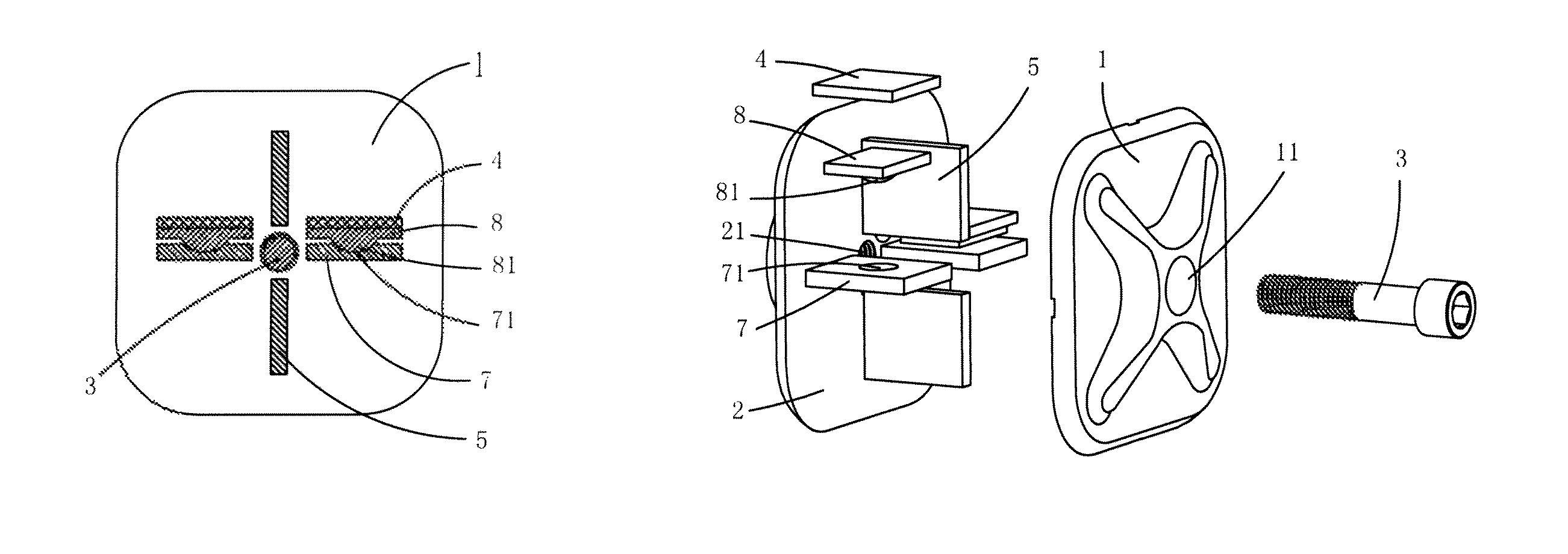
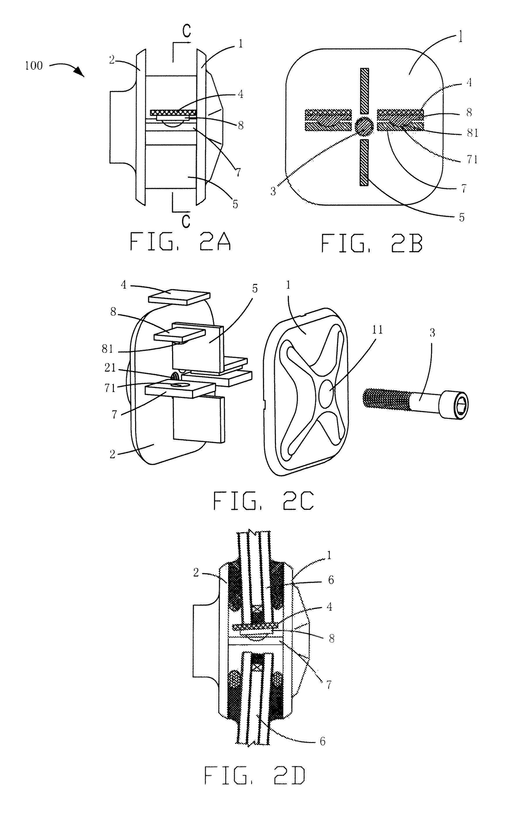
[0026]Referring to FIGS. 2A through 2C, a fastening device 100 is used to retain curtain wall units 6. The fastening device 100 includes a first clamping plate 1, a second clamping plate 2, a screw 3, two washers 4, two spacer plates 5, two first support plates 7 and two second support plates 8.
[0027]The first clamping plate 1 is substantially rectangular and defines a through hole 11 at a center of the first clamping plate 1.
[0028]The second clamping plate 2 has substantially the same shape as the first clamping plate 1 and defines a threaded hole 21 at a center thereof corresponding to the through hole 11.
[0029]The screw 3 extends through the through hole 11 and threadedly engaged in the threaded hole 21, such that the second clamping plate 2 is fixed and spaced apart from the first clamping plate 1.
[0030]The two spacer plates 5 are positioned at a side surface of the second clamping plate 2 and each extending vertically substantially perpendicular to the second clamping plate 2. ...
second embodiment
[0037]Referring to FIGS. 3A through 3D, a fastening device 200 is similar to the fastening device 100, except for that, the ball member 271 is formed on the first support plate 27, and the depression 281 is defined on a side of the second support plate 28. The ball member 271 is partially received in the depression 281, such that the second support plate 28 is hinged to the first support plate 27.
third embodiment
[0038]Referring to FIGS. 4A through 4D, a fastening device 300 is similar to the fastening device 100, except for that, the first support plate 37 defines a first depression 371 on a side thereof, the second support plate 38 defines a second depression 381 on a side thereof corresponding to the first depression 371, the fastening device 300 further includes a ball member 39 rotatably received in the first depression 371 and the second depression 381, such that the second support plate 38 is hinged to the first support plate 37.
[0039]Referring to FIG. 5, a four embodiment of a fastening device 400 is similar to the fastening device 100, except for that, it further includes two positioning plates 483 extending upwardly form two opposite ends of the second support plate 48. The two positioning plates 483 and the second support plate 48 corporately defines a mounting groove 485 to receive the curtain wall units 6, such that the curtain wall units 6 are firmly fixed to the second support...
PUM
 Abstract
Description
Claims
Application Information
 - R&D
- Intellectual Property
- Life Sciences
- Materials
- Tech Scout
- Unparalleled Data Quality
- Higher Quality Content
- 60% Fewer Hallucinations
Browse by: Latest US Patents, China's latest patents, Technical Efficacy Thesaurus, Application Domain, Technology Topic, Popular Technical Reports.
© 2025 PatSnap. All rights reserved.Legal|Privacy policy|Modern Slavery Act Transparency Statement|Sitemap|About US| Contact US: help@patsnap.com