
Device for supplying a patient with breathing gas

a technology for supplying gas to patients and patients, applied in the field of respiration system, can solve the problems of complex manufacture of prior-art covers, and achieve the effects of reducing the thickness of elastomer materials, improving gas tightness between the housing and the cover, and good sealing

Active Publication Date: 2012-07-24
DRAGERWERK AG
View PDF6 Cites 2 Cited by
  • Summary
  • Abstract
  • Description
  • Claims
  • Application Information

AI Technical Summary

Benefits of technology

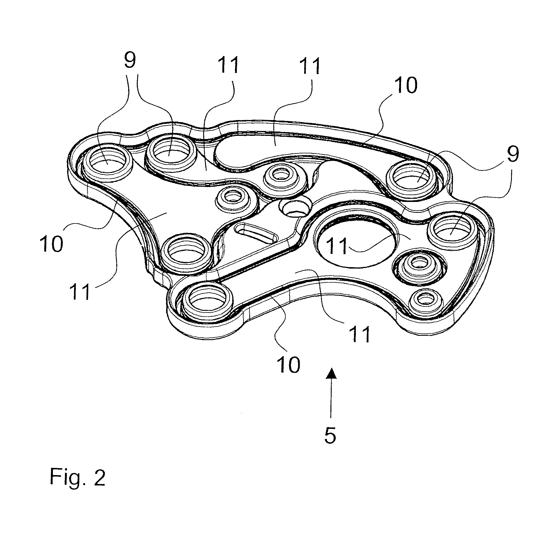
[0025]The advantage of the present invention is that the cover consists of a plate-like elastomer material, which is pulled over the housing. To seal the gas ducts, groove-like depressions, which extend along the partitions and reduce the material thickness of the elastomer material in this area, are provided in the elastomer material. The depressions are pulled over the front sides of the partitions when the cover plate is placed on the housing. Good sealing is thus achieved in the connection area between the cover plate and the partitions. The pressing force exerted by the elastomer material on the partitions is increased due to the fact that the full material thickness and hence rigidity of the elastomer material is present outside the depressions. The elastomer material is thus fixed by the intrinsic stress at the partitions. The cover plate specified in the present invention can be manufactured in a simple manner according to the injection molding process. Suitable elastomers are silicone and EPDM (ethylene propylene diene monomer (M-class) rubber). Tolerances at the housing can be better compensated by the elastomer material than with a cover plate consisting of a solid material, with inserted, elastic packing cords.
[0026]The wall sections of the depressions in the connection area with the partitions advantageously also have additionally a sealing contour. This sealing contour may be a sealing lip extending along the partitions or a groove. The gas tightness between the housing and the cover is further improved by the sealing contour. It is especially advantageous that only the cover has to be replaced in case of possible damage to the sealing contour or the wall sections, while the substantially more expensive housing, which is sometimes provided with valves, can be used further.
[0027]The cover may advantageously be provided with holes in order to establish a connection to the gas ducts extending within the housing.
[0028]In addition, a closing plate with gas ports can be placed on the cover, the gas ports being located in the area of the holes of the cover.

Problems solved by technology

The manufacture of the prior-art cover is complicated because the packing cords must be vulcanized with precision into grooves prepared in advance in the cover plate.

Method used


Image

  • Device for supplying a patient with breathing gas
  • Device for supplying a patient with breathing gas
  • Device for supplying a patient with breathing gas

Examples


Embodiment Construction

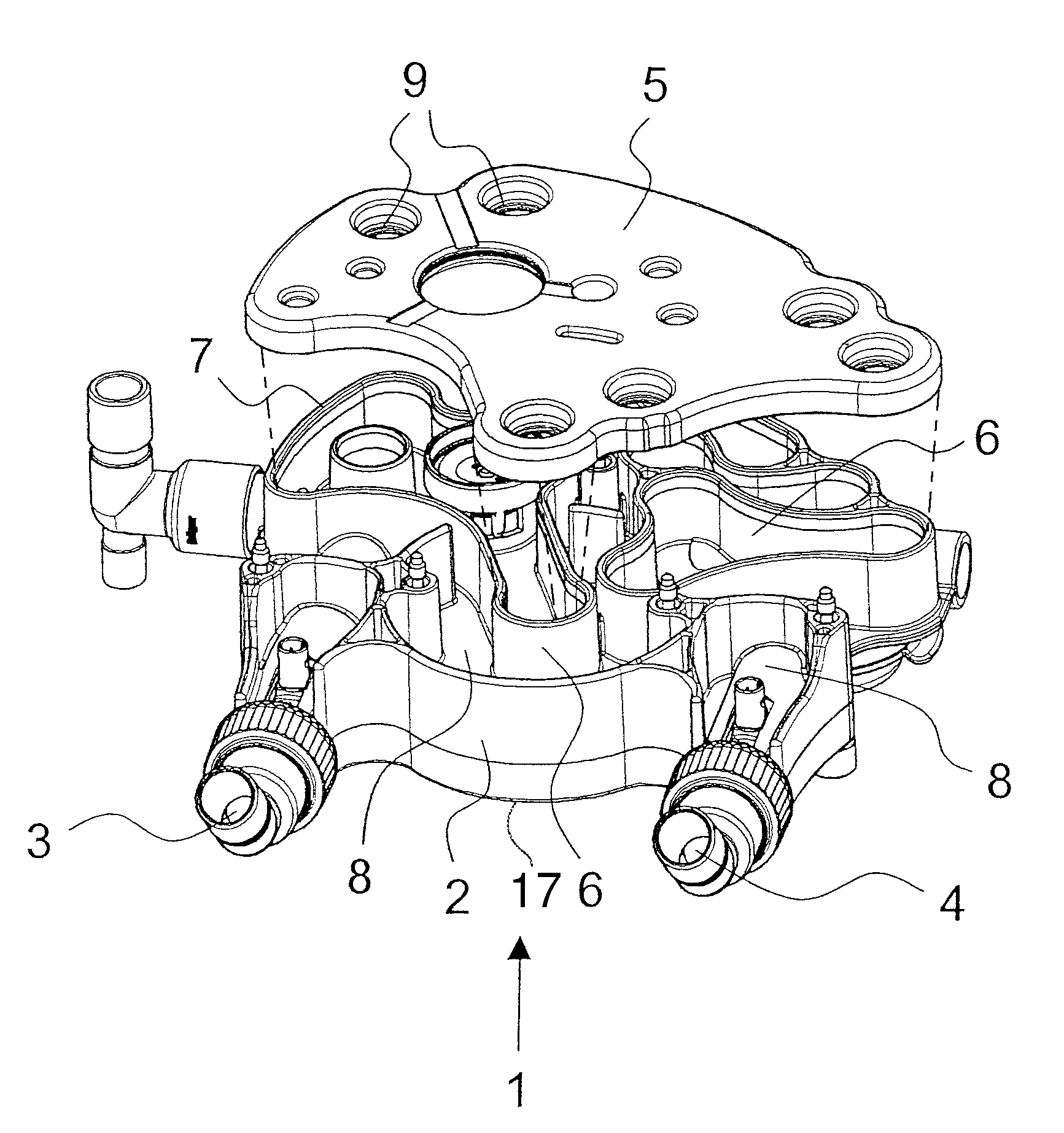
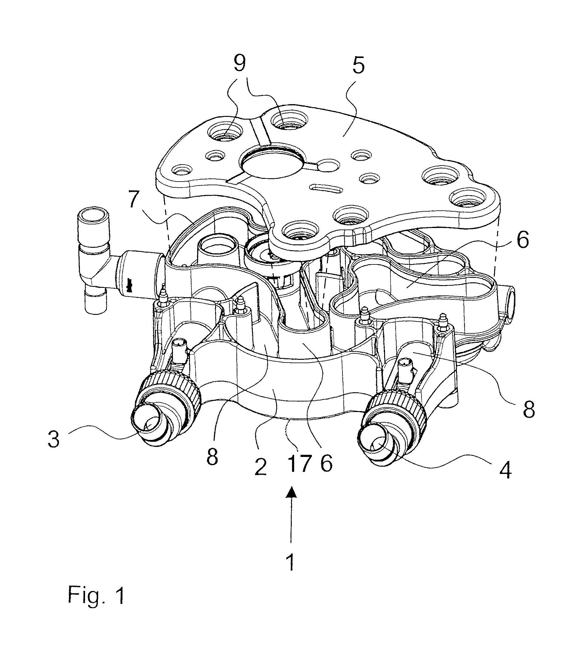
[0036]Referring to the drawings in particular, FIG. 1 shows a perspective view of a closed respiration system 1 from the bottom for supplying a user, not shown more specifically, with breathing gas. The closed respiration system 1 comprises a housing 2 with an expiration port 3 and an inspiration port 4 as well as a cover 5 made of silicone, which is pulled over the housing 2. Partitions 6 are located within the housing 2 and extend from a base 17 of the housing 2 in order to form meandering gas ducts 8 between the expiration port 3 and the inspiration port 4. The partitions 6 are designed such that their front sides or edges 7 are open towards one side. Wall surfaces 16 of the partition walls 6 and the housing base 17 form the gas ducts 8 together with the cover 5. The gas ducts 8 without the cover 5 are U-shaped with the partitions 6 forming legs of the U-shape. The cover 5 is provided with holes 9 in order to make access possible to the gas ducts 8 in order for gas to be able to ...


PUM

PropertyMeasurementUnit
thicknessaaaaaaaaaa
areaaaaaaaaaaa
rigidityaaaaaaaaaa

Abstract

A device for supplying a patient with breathing gas, which has a housing provided with gas ducts and a corresponding cover (5), shall be improved such that the cover (5) can be manufactured in a simple manner and possesses good sealing properties. To accomplish the object, provisions are made for the cover (5) to consist of a one-piece, plate-like elastomer material and for groove-like depressions (10) extending in the direction of partitions (6) to be present as a seal for the gas ducts (8).

Description

CROSS REFERENCE TO RELATED APPLICATIONS[0001]This application claims the benefit of priority under 35 U.S.C. §119 of German Patent Application DE 10 2007 005 819.7 filed Feb. 6, 2007, the entire contents of which are incorporated herein by reference.FIELD OF THE INVENTION[0002]The present invention pertains to a respiration system, which is provided with gas ducts and is used in anesthesia apparatuses or respirators for supplying a patient with breathing gas.BACKGROUND OF THE INVENTION[0003]A respiration system of the type appears from EP 643 978 B1. It comprises a housing provided with gas ducts and a cover plate, which seals the interior space of the housing against the environment. To form the gas ducts, the housing has partitions, which extend, starting from the bottom of the housing, vertically up to the top side of the housing. To seal the gas ducts, the cover plate is provided with packing gaskets (cords) or seals, which extend corresponding to the partitions. The cover plate...

Claims


Application Information

Patent Timeline
Patent Type & Authority Patents(United States)
IPC IPC(8): A61M16/01B29C45/14
CPCA61M16/01A61M16/08
Inventor SCHNAARS, HENRYKTURKER, AHMETREICHERT, DIRK-STEFAN
Owner DRAGERWERK AG
Learn More