Power supply unit, hard disk drive and method of switching the power supply unit
a power supply unit and hard disk drive technology, applied in the direction of electric variable regulation, process and machine control, instruments, etc., can solve the problems of driving losses, shortcoming in circuit structure, short circuit short circuit, etc., and achieve the effect of improving efficiency during light loads
- Summary
- Abstract
- Description
- Claims
- Application Information
AI Technical Summary
Benefits of technology
Problems solved by technology
Method used
Image
Examples
embodiment 1
[0024]Herein below, preferable embodiments of the present invention will be explained with reference to the drawings.
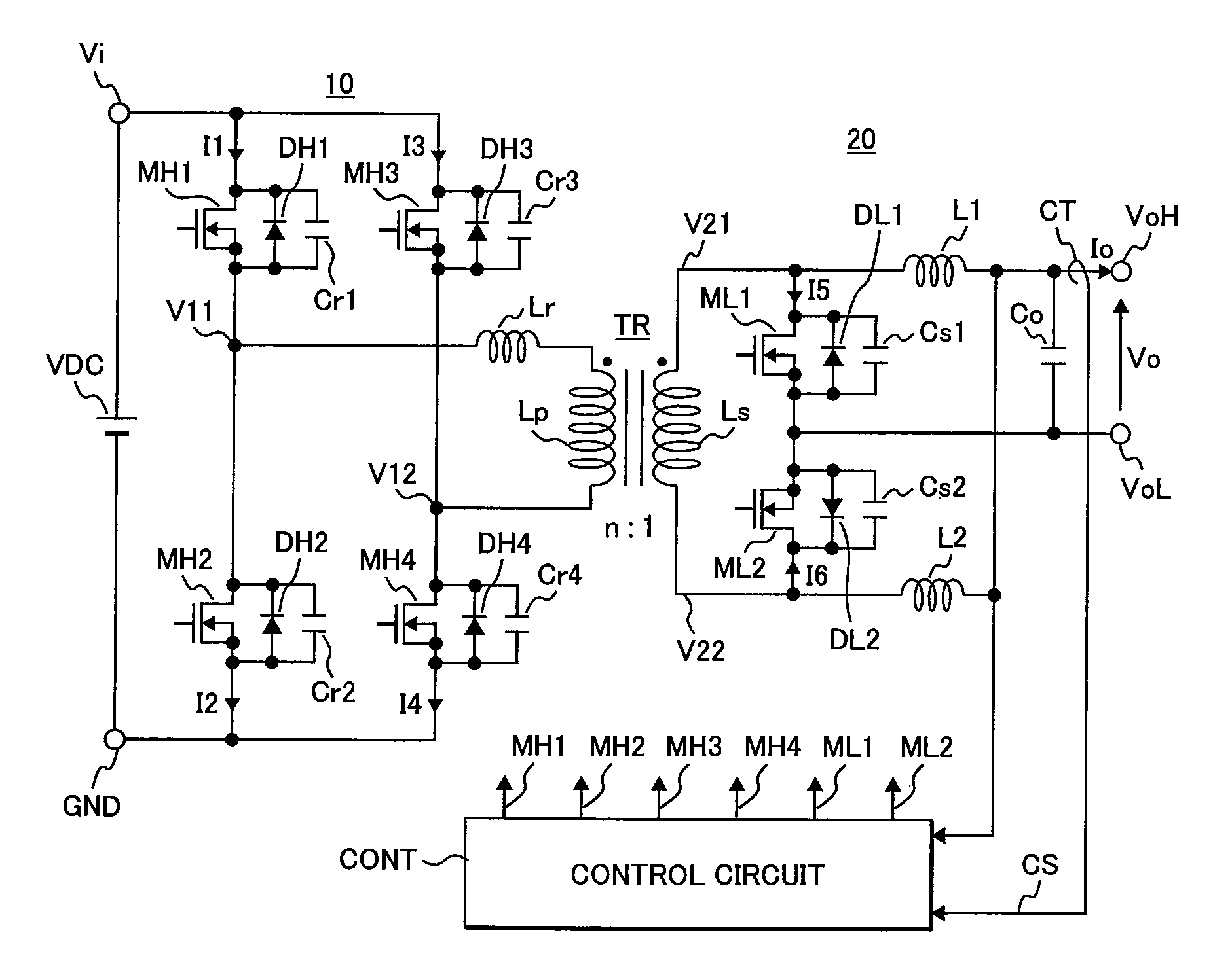
[0025]FIG. 1 shows a first embodiment of a power supply unit of an isolation type DC-DC converter to which the present invention is applied. In the drawing, TR is a transformer, 10 is a full bridge circuit that AC drives a primary coil Lp in the transformer TR, 20 is a current doubler type rectifier and smoothing circuit that synchronously rectifies AC voltages induced at a secondary coil Ls in the transformer TR and converts the same into DC voltages and CONT is a control circuit that controls the operation timings of switch MOSFETs MH1˜MH4 constituting the full bridge circuit 10 and synchronous rectifier switch MOSFETs ML1 and NL2 in the rectifier and smoothing circuit 20.
[0026]The full bridge circuit 10 is constituted by N channel MOSFETs MH1 and MH2, and MH3 and MH4 that are respectively connected in series between an input terminal Vi and a primary reference pote...
embodiment 2
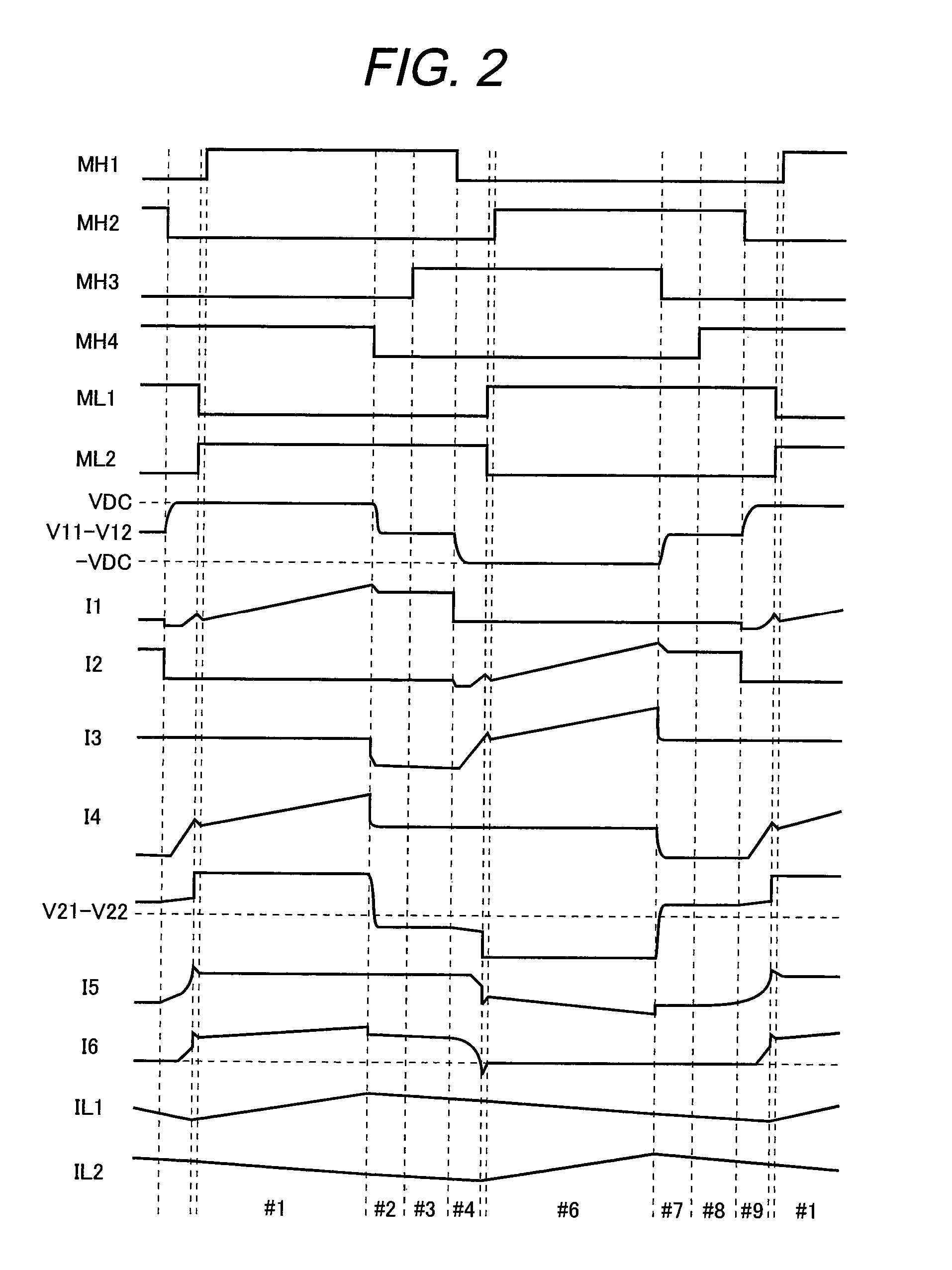
[0064]The second embodiment is shown in FIG. 11. In FIG. 11, the same constitutional elements as those in FIG. 1 are denoted by the same reference characters. A different point of FIG. 11 from FIG. 1 is that the secondary coil of the transformer TR is changed to coils Ls1 and Ls2 with a tap. For this reason, in the rectifier and smoothing circuit 20, the synchronous rectifier switch ML1 and ML2 are connected in series between both terminals of the secondary coil, and the center tap of the secondary coil is connected via a choke coil L to one terminal of the output capacitor Co. Further, the other terminal of the output capacitor Co is connected to a midpoint of the synchronous rectifier switch ML1 and ML2. In the present embodiment, likely, by detecting such as the load states and the DC voltage state at the primary side, the control circuit CONT generates the operation timing signals for the switches MH1˜MH4, ML1 and ML2 as shown in FIG. 2 when the load is at a (around) rated load ...
embodiment 3
[0066]The present embodiment is shown in FIG. 12. FIG. 12 is an embodiment in which the present invention is applied to an HDD (Hard Disk Drive). A power supply system in an HDD constitutes a power supply system of parallel redundant structure that receives AC voltage and outputs an output voltage Vo via PEC (Power Factor Correction) circuits PFC1 and PFC2 and isolation type DC-DC converters Iso DC-DC1 and Iso DC-DC2 that are the power supply units as explained in the embodiment 1 or 2. To the output voltage Vo a backup power supply BUPS mounting a battery is connected as a power outage measure. Further, the output voltage Vo supplies an electric power to the HDDs HDD1˜DHHn via nonisolation type DC-DC converters DC-DC11˜DC-DC1m as well as supplies electric powers of different voltages suitable for respective objects via nonisolation type DC-DC converters DC-DC1˜DC-DCn to a board constituted by such as a processor administering control for storing data in the HDDs and high speed larg...
PUM
 Abstract
Description
Claims
Application Information
 - R&D
- Intellectual Property
- Life Sciences
- Materials
- Tech Scout
- Unparalleled Data Quality
- Higher Quality Content
- 60% Fewer Hallucinations
Browse by: Latest US Patents, China's latest patents, Technical Efficacy Thesaurus, Application Domain, Technology Topic, Popular Technical Reports.
© 2025 PatSnap. All rights reserved.Legal|Privacy policy|Modern Slavery Act Transparency Statement|Sitemap|About US| Contact US: help@patsnap.com


