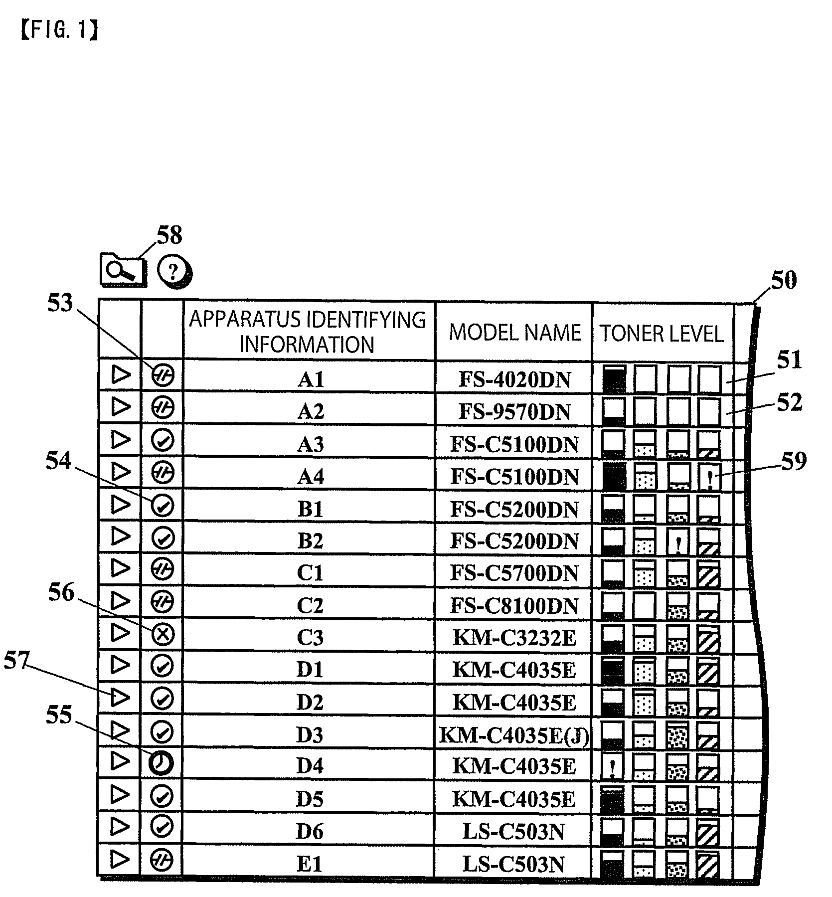
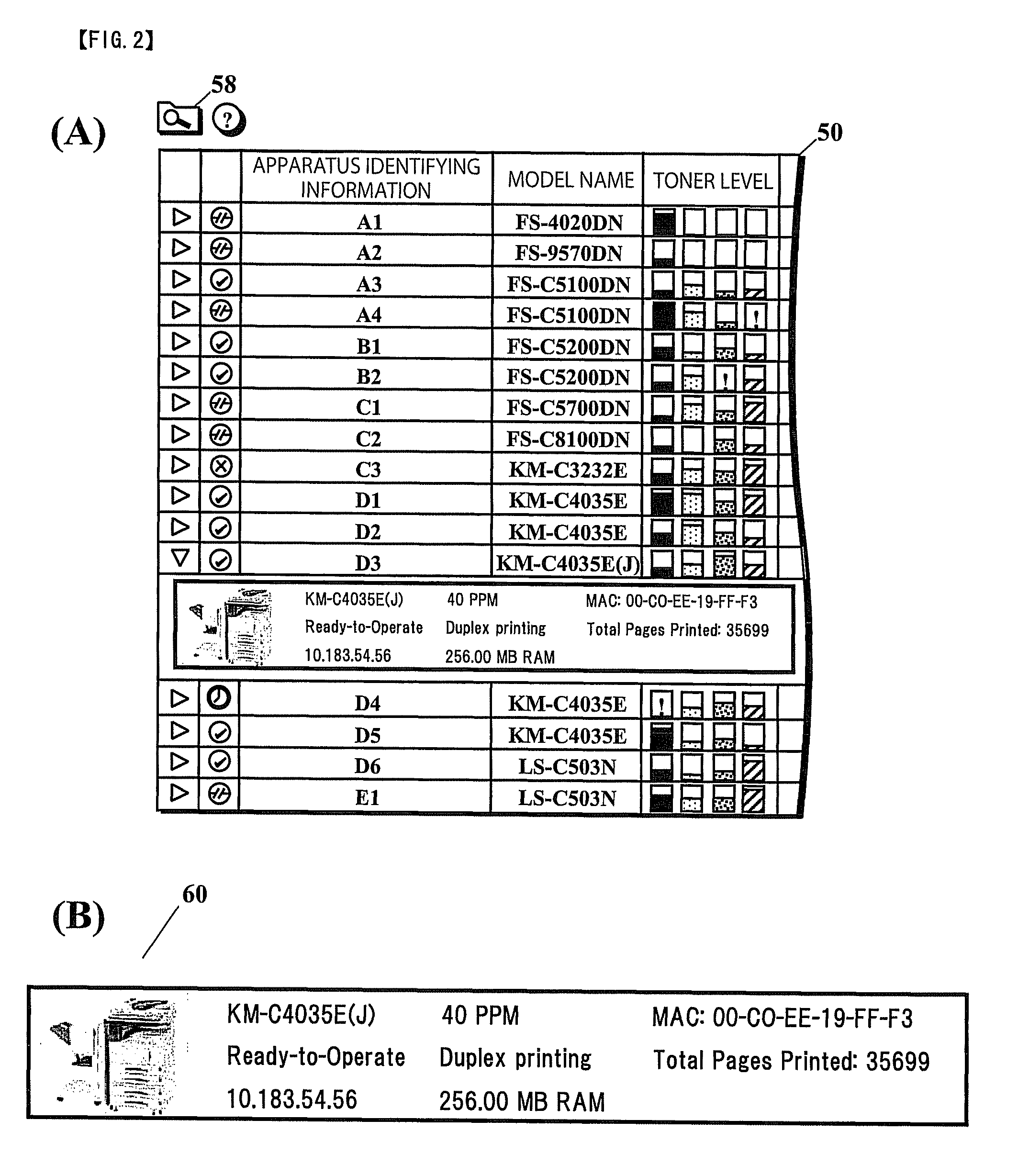
Displaying status icons of remaining consumables for plural image forming apparatuses
a technology status icons, which is applied in the field of image forming system, can solve the problems of difficult for users to easily and quickly select one of image forming apparatuses on the network, and achieve the effect of easy and quick selection, easy and quick management of remaining amounts of toner
- Summary
- Abstract
- Description
- Claims
- Application Information
AI Technical Summary
Benefits of technology
Problems solved by technology
Method used
Image
Examples
first embodiment
[0027]FIG. 4 is a schematic diagram of a configuration of an image forming system according to a first embodiment of the present invention.
[0028]In the image forming system, image forming apparatuses 201 to 204, PC 301 and PC 302, and a management apparatus 40 are connected to a local area network (LAN) 10. Image forming apparatuses 201 to 204 can be selectively used from PC 301 and PC 302. The management apparatus 40 collects various types of information, such as information regarding users of the image forming apparatuses 201 to 204, the number of sheets to be used, the remaining amounts of toner, and the occurrence of an error, via the LAN 10 so that the management information can be centralized. Further, among the various types of information collected by the management apparatus 40, apparatus status information such as the remaining amounts of toner and the occurrence of an error, apparatus identifying information, and apparatus performance information are transferred to PC 301...
second embodiment
[0072]FIG. 7 is a display screen 50A on which various types of information regarding each of the plurality of image forming apparatuses obtained from the image forming apparatuses via a network is displayed according to a second embodiment of the present invention. The display screen 50A corresponds to the display screen 50 illustrated in FIG. 1.
[0073]In the display screen 50A, when an image forming apparatus is disconnected from a network or is in an abnormal state, icons representing toner levels for the image forming apparatuses are grayed out (display inactive). This allows a user to select an image forming apparatus without referring to apparatus state icons 53 to 56.
[0074]The present configuration is similar to that of the first embodiment described above. That is, when an expansion icon 57 is clicked on, detailed performance information can be displayed in an accordion-like fashion similar to that of the first embodiment.
third embodiment
[0075]FIG. 8 is a display screen 50B on which various types of information regarding each of the plurality of image forming apparatuses obtained from the image forming apparatuses via a network is displayed according to a third embodiment of the present invention. The display screen 50B corresponds to the display screen 50A illustrated in FIG. 7.
[0076]In the display screen 50B, for each image forming apparatus, a portion of apparatus performance information is displayed so as to be aligned with icons representing C / M / Y / K toner levels. The display screen 50B includes, as device performance information, color / monochrome (C / M) printing speed (which is expressed in PPM), and availability of finishing-process functions (punching and stapling functions).
[0077]For an image forming apparatus that is ready to operate, an estimated value of print waiting time, which is expressed in minutes (m), is further displayed. Furthermore, apparatus state icons are aligned in a column adjacent to the co...
PUM
 Abstract
Description
Claims
Application Information
 - R&D
- Intellectual Property
- Life Sciences
- Materials
- Tech Scout
- Unparalleled Data Quality
- Higher Quality Content
- 60% Fewer Hallucinations
Browse by: Latest US Patents, China's latest patents, Technical Efficacy Thesaurus, Application Domain, Technology Topic, Popular Technical Reports.
© 2025 PatSnap. All rights reserved.Legal|Privacy policy|Modern Slavery Act Transparency Statement|Sitemap|About US| Contact US: help@patsnap.com


