
Warhead

a technology of warheads and missiles, applied in the field of warheads, can solve the problem that the number of missiles is restricted to defeating relatively large numbers

Active Publication Date: 2012-06-12
BAE SYST BOFORS
View PDF13 Cites 10 Cited by
  • Summary
  • Abstract
  • Description
  • Claims
  • Application Information

AI Technical Summary

Benefits of technology

The present invention relates to a more versatile warhead that can defeat a variety of targets, including cruise missiles, signal-seeking missiles, controlled glide bombs, and large aircraft. The warhead comprises a first part with a first explosive section and a casing containing multiple projectiles, and a second part with an element designed to control the warhead's working based on a control signal. The second part can also have a second explosive section. The warhead can be designed to detonate the first and / or second explosive section as a function of the control signal. The warhead can be used against both hard and soft targets, and its impact energy can be selected and controlled based on the target's impact velocity.

Problems solved by technology

However, the missile is confined to defeating relatively large, just such large, heavy and slow-moving targets such as tanks, which are provided with active armor.

Method used


Image

  • Warhead
  • Warhead
  • Warhead

Examples


Embodiment Construction

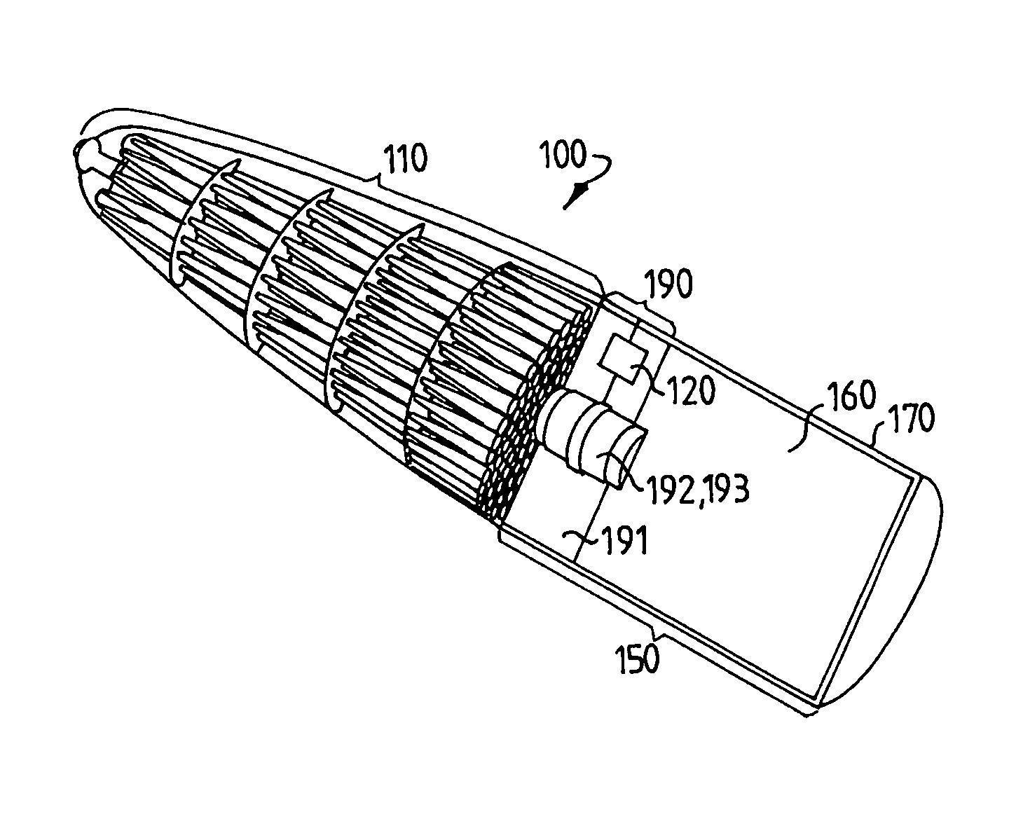
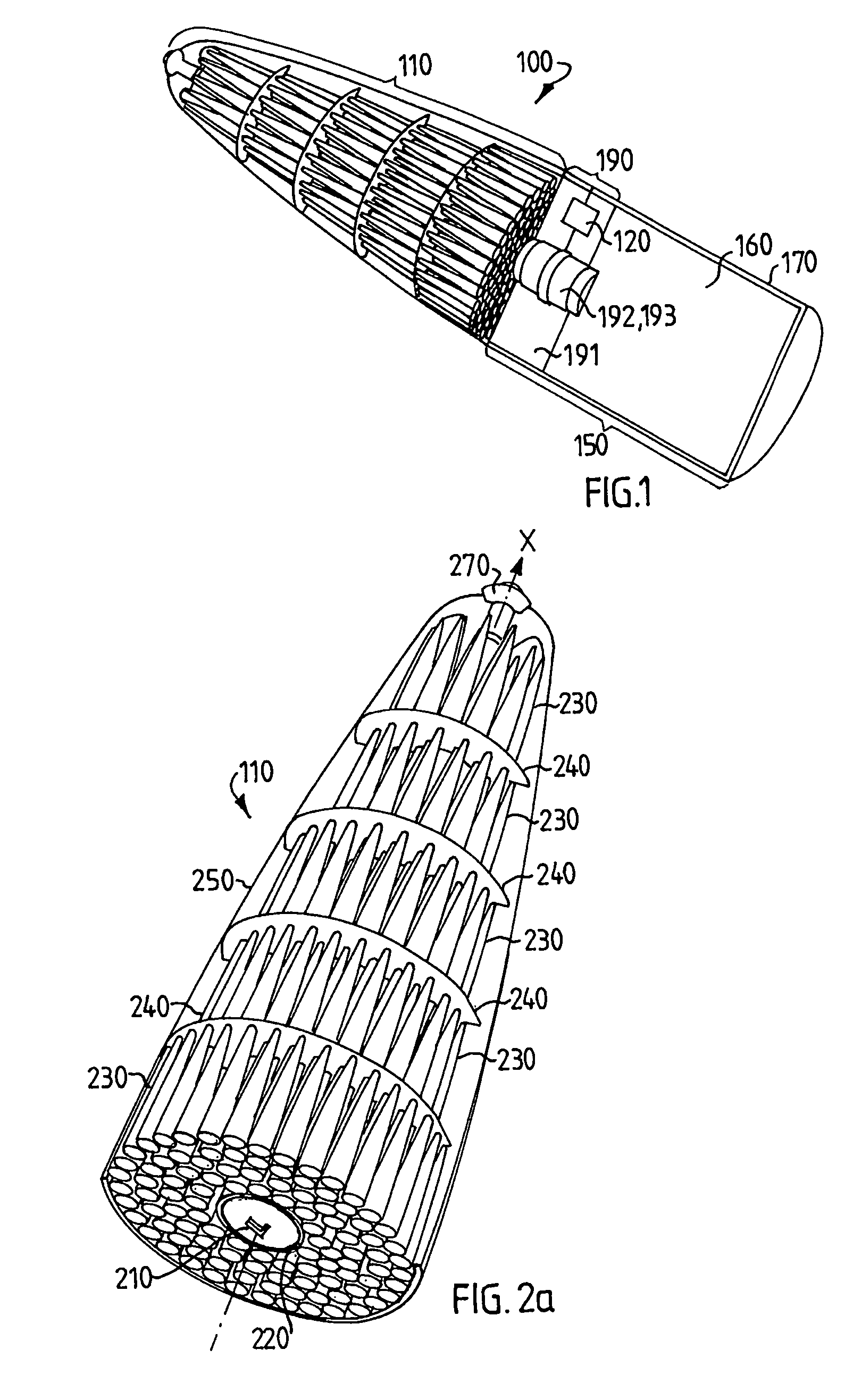
[0039]FIG. 1 shows a schematic view of a warhead. 100 according to one embodiment of the invention. The warhead as described here comprises three sections. A first section 110 is a main portion. The first section may also be termed a first module. A second section 150 comprises an explosive charge 160 enclosed by a casing 170. The second section may also be termed a second module. A third section 190 comprises, among other things, a detonation-preventing barrier 191 between the first and second section. The third section 190 comprises, among other things, a control element 120 for controlling the detonation, and a booster 192 and priming device 193. The third section is incorporated into the second module.

[0040]According to one embodiment the total weight of the warhead is in the range from 1 to 5 kg. The total weight of the warhead is preferably in the range from 3 to 4 kg. According to one embodiment the total weight of the warhead is in the range from 5 to 10 kg. According to one...


PUM


Abstract

The invention relates to a warhead comprising a first and a second part, the parts being arranged relative to one another along a longitudinal axis, the first part comprising a first explosive section, a casing, and a plurality of projectiles enclosed in the casing. The second part comprises an element designed to control the working of the warhead as a function of a control signal. The fact that the functioning of the warhead can be controlled means that the warhead can defeat a plurality of different targets, which makes the warhead versatile.

Description

TECHNICAL FIELD[0001]The invention relates to a warhead.[0002]The invention also relates to a missile which comprises the warhead.[0003]The invention also relates to a system in which the warhead is used.BACKGROUND ART[0004]U.S. Pat. No. 4,638,737 describes an anti-armor missile designed to defeat an active armor placed on a target, such as a tank.[0005]The missile is designed to first defeat the active armor on the tank by means of a cluster of projectiles before allowing a main charge to defeat the primary armor.[0006]However, the missile is confined to defeating relatively large, just such large, heavy and slow-moving targets such as tanks, which are provided with active armor.[0007]The front part of the missile is designed for controlled and systematic opening, the leading projectiles continuing towards the target at a certain velocity, whilst the rear main charge is first braked by a braking force and then re-propelled in order to thereby strike the target later than the leadin...

Claims


Application Information

Patent Timeline
Patent Type & Authority Patents(United States)
IPC IPC(8): F42B12/62F41H11/02F42BF42B12/20F42B12/60F42B12/64
CPCF41H11/02F42B12/202F42B12/204F42B12/64F42B12/58F42B12/60F42B12/62F42B12/205
Inventor GUSTAFSSON, LENNARTRONN, TORSTEN
Owner BAE SYST BOFORS
Learn More