Device for igniting a fuel/air mixture

a technology of fuel/air mixture and device, which is applied in the direction of engine ignition, fuel supply apparatus, electrical apparatus, etc., can solve the problems of limited high voltage transmission, difficult electrode arrangement in relation to the geometry of the combustion chamber, and limited space in the cylinder head and the choice of insulator material, etc., to achieve the effect of less easily damaged

Active Publication Date: 2012-06-05
GE JENBACHER
View PDF19 Cites 3 Cited by
  • Summary
  • Abstract
  • Description
  • Claims
  • Application Information

AI Technical Summary

Benefits of technology

[0009]Therefore, the object of the present invention is to provide a device of the kind set forth in the opening part of this specification, in which the electronic components of the corona discharge can be less easily damaged.
[0012]Due to the direct inlet of fuel, the corona discharge in the precombustion chamber is no longer dependent on fuel diffusing out of the main combustion chamber of the internal combustion engine into the precombustion chamber, and it is possible to have recourse directly to fuel introduced by way of the precombustion fluid inlet. In practice, very frequently pure fuel or at least a richer fuel / air mixture is passed into the precombustion chamber than is passed into the main combustion chamber. The expression “richer fuel / air mixture” is used to mean that the ratio of fuel to oxygen is greater than in the case of a leaner mixture. A richer mixture improves the firing condition and reduces the energy required for ignition.
[0013]So that the corona in the precombustion chamber can propagate well and can develop well, it has proven to be desirable if the precombustion chamber has regions with different cross-sectional internal surfaces, in which the cross-sectional internal surface is smaller in the region of the at least one opening than the cross-sectional internal surface in the region in which the electrode passes into the precombustion chamber. In that respect, in a variant it can be provided that the precombustion chamber has a multi-part configuration. For example, there can be a first precombustion chamber which is arranged in the region in which the electrode passes into the precombustion chamber and a second precombustion chamber in the region of the at least one opening. Desirably, the volume of the first precombustion chamber is larger than that of the second precombustion chamber. In that way, corona ignition can take place particularly efficiently. In that respect it has proven to be particularly desirable if the fluid inlet opens into the first precombustion chamber.
[0017]It is precisely in precombustion chambers that non-homogenous fuel distribution can occur so that regions can occur with higher λ-values and lower λ-values (the λ-value is used to denote the combustion air ratio, that is to say the ratio of air to fuel for combustion, wherein λ=1 represents a stoichiometric ratio, λ greater than 1 represents an insufficiency of air, and λ, smaller than 1 represents an excess of air). Corona ignition has the advantage that it is precisely those regions with a lower λ, that are ignited first and thus ideal ignition takes place. The streamers are thus optimally distributed in space. Due to the shape of the electrodes, that is to say the actual electrode which extends into the precombustion chamber and the counterpart electrode which is generally formed by the precombustion chamber wall, that also affords advantages in terms of electric field control.

Problems solved by technology

The high voltages however are limited by a number of factors.
The space required in the cylinder head and the choice of the insulator material sets limits in regard to the transmission of those high voltages.
In the case of very large combustion chambers as occur for example in stationary gas Otto engines which represent a main area of use of the invention, the electrode arrangement in relation to the combustion chamber geometry is problematical as, on the one hand, the piston covers very great distances and, on the other hand, the required voltages are very high due to the spatial arrangement involved.
An internal combustion engine operated in that way tends to have ignition misfires in operation.
In the case of conventional spark discharge, such deposits are quickly burnt away.
Deposits which can prevent proper fluid exchange between the precombustion chamber and the combustion chamber can therefore have the result that, because of the inadequate fluid exchange, the voltage regulator re-adjusts the supply of voltage to the electrode.
In the extreme case, that can mean that the electrode and the basic highly sensitive electronic components thereof are permanently damaged.

Method used


Image

  • Device for igniting a fuel/air mixture
  • Device for igniting a fuel/air mixture
  • Device for igniting a fuel/air mixture

Examples


Embodiment Construction

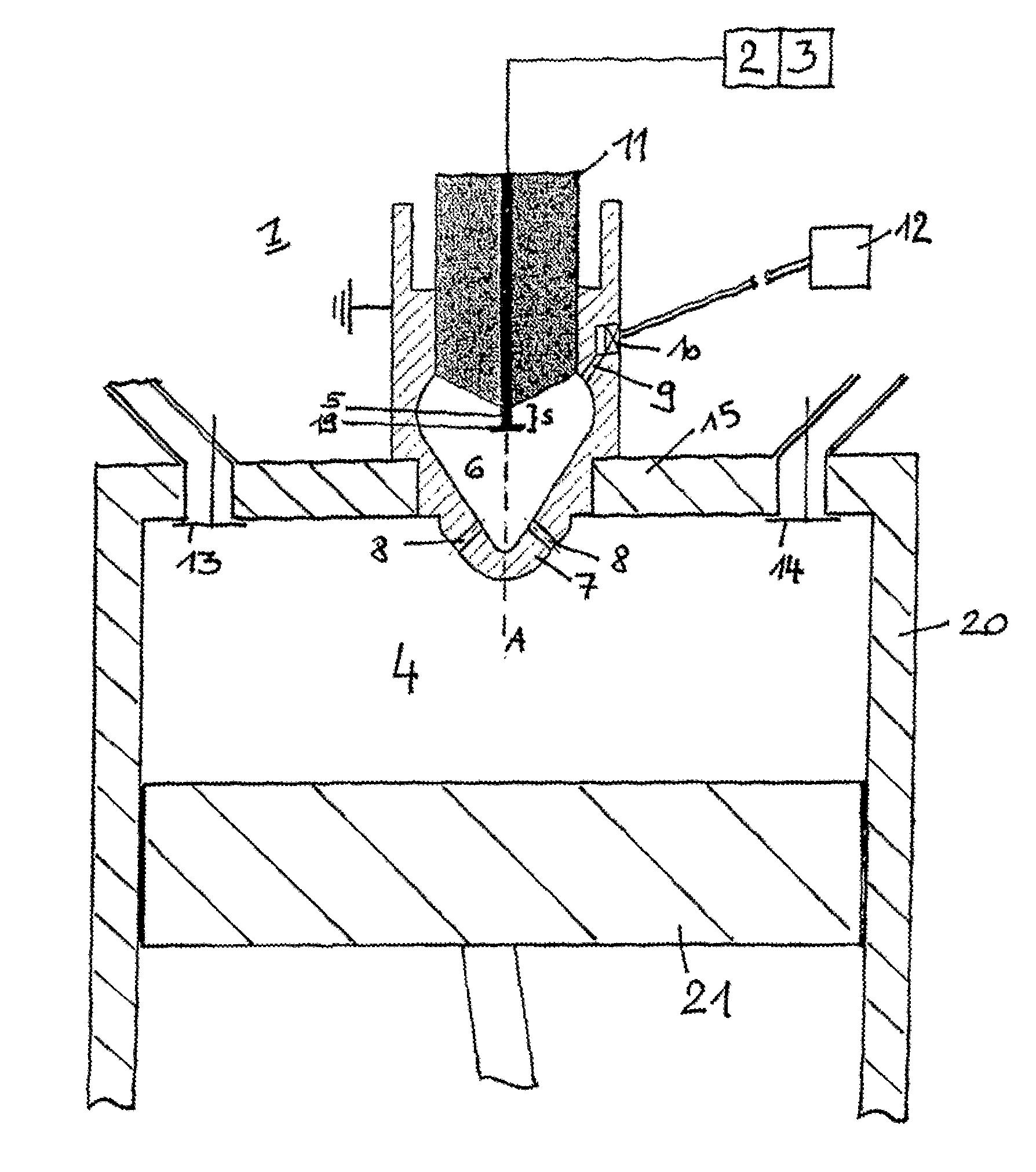
[0022]FIG. 1 shows a device 1 for the ignition of a fuel / air mixture in the combustion chamber 4 of an internal combustion engine which is shown only roughly in diagrammatic form. For reasons of clarity of the drawing, only one cylinder 20 is shown, in which a piston 21 moves up and down. The device 1 includes an electrode 5 which is connected to a voltage source 2 by way of an energy transfer unit 25 (here in the form of an electric lead). The electrode 5 extends by a portion S into the precombustion chamber 6 of the device 1. The precombustion chamber 6 is region-wise separated from the combustion chamber 4 by the wall 7. The wall 7 forms the counterpart electrode so that an electric field is produced between the electrode 5 and the wall 7 which is grounded when the voltage source 2 supplies the electrode 5 with voltage. With a sufficient field strength, a corona is formed in the precombustion chamber 6. For that purpose, there is also provided a control device or regulating devic...


PUM


Abstract

The invention relates to a device for igniting a fuel / air mixture in the combustion chamber of an internal combustion engine. The device includes an electrode which is connected to a voltage source and extends into a precombustion chamber, and the precombustion chamber is separated at least in some regions from the combustion chamber by a wall. A control device or a regulating device is provided which controls the voltage supply to the electrode such that a corona discharge is carried out in the precombustion chamber. The wall has at least one opening for exchanging fluids between the combustion chamber and precombustion chamber, and a fluid inlet opens into the precombustion chamber.

Description

[0001]This application is a Continuation of International application No. PCT / AT2009 / 000283, filed Jul. 22, 2009, the entire disclosure of which is incorporated herein by reference.BACKGROUND OF THE INVENTION[0002]The invention concerns a device for igniting a fuel / air mixture in the combustion chamber of an internal combustion engine, and the device includes an electrode connected to a voltage source and extending into a precombustion chamber. The precombustion chamber is separated at least region-wise from the combustion chamber by a wall, and a control device or regulating device regulates the supply of voltage to the electrode in such a way that a corona discharge takes place in the precombustion chamber. The wall has at least one opening for the exchange of fluids between the combustion chamber and the precombustion chamber. The invention further concerns a method of igniting a fuel / air mixture in the combustion chamber of an internal combustion engine. Finally the invention co...

Claims


Application Information

Patent Timeline
IPC IPC(8): F02B19/12
CPCF02B19/1014F02B19/12F02P9/007F02P13/00F02M21/0275F02P15/003Y02T10/125Y02T10/32F02M21/0209Y02T10/12Y02T10/30
Inventor GRUBER, FRIEDRICHLU, HANGKRAUS, MARKUS
Owner GE JENBACHER
Why Eureka
Try Eureka