Anti-glare protection device

a protection device and anti-glare technology, applied in the field of anti-glare protection devices, can solve the problems of product failure, and achieve the effect of improving protection quality

Active Publication Date: 2012-05-22
OPTREL AG
View PDF11 Cites 4 Cited by
  • Summary
  • Abstract
  • Description
  • Claims
  • Application Information

AI Technical Summary

Benefits of technology

[0009]It is therefore an object of the invention to overcome the limitations of the prior art, and to create an anti-glare protection device of the type mentioned initially that provides increased usability of a welding mask incorporating the anti-glare protection device.
[0010]A further object of the invention is to provide an anti-glare protection device with improved protection quality.
[0014]This gives the possibility to adjust or fine-tune the transmission in automatic mode within a small range. In a preferred implementation, this range is limited to + / −1 Shade Numbers (S). This allows the welder to adapt the mask to his personal preference and comfort. As an example, it is a well known fact that older welders prefer a slightly higher filter transmission than younger ones due to the ageing process of the human eye. In a preferred implementation, the same knob as for the adjustment of the S in manual mode is used, reducing complexity and cost for moving parts.

Problems solved by technology

However, such products have not met with success, since fully automatic filters are only applicable in situations and welding positions where the mask's sensors correctly capture the brightness of the welding process.
Furthermore, in a fully automatic anti-glare device, the welder's specific preference with respect to the perceived brightness is not accounted for.

Method used


Image

  • Anti-glare protection device
  • Anti-glare protection device
  • Anti-glare protection device

Examples


Embodiment Construction

[0009]It is therefore an object of the invention to overcome the limitations of the prior art, and to create an anti-glare protection device of the type mentioned initially that provides increased usability of a welding mask incorporating the anti-glare protection device.

[0010]A further object of the invention is to provide an anti-glare protection device with improved protection quality.

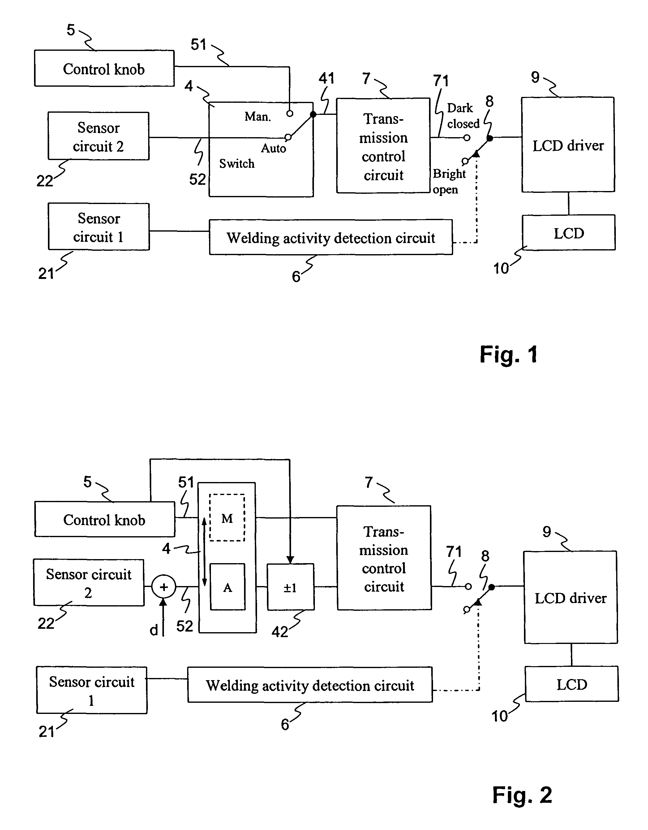
[0011]These objects are achieved by an anti-glare protection device for a welding mask, comprising a transmission control circuit for determining a darkening signal from a control signal, a welding activity detection circuit for detecting a welding activity, based on a first sensor signal from a first sensor circuit, wherein the welding activity detection circuit is arranged to control, by means of an activation switch, whether either the darkening signal or a signal corresponding to an undarkened optical filter is input to a filter drive circuit. The anti-glare protection device further comprises s...


PUM


Abstract

An anti-glare protection device for a welding mask includes a transmission control circuit for determining a darkening signal from a control signal, a welding activity detection circuit (6) for detecting a welding activity, based on the output of a first sensor circuit. The welding activity detection circuit is arranged to control, via an activation switch, whether either the darkening signal or a signal corresponding to an undarkened optical filter is input to a filter drive circuit. The filter drive circuit drives a controllable optical filter to a transmission value according to the signal input to the filter drive circuit. A manual input device allows a user to manually adjust a user selected signal. A second sensor circuit determines a sensed signal. A manually operable mode selection switch for selecting either, in a manual mode, the user selected signal or, in an automatic mode, the sensed signal to be used as the control signal to the transmission control circuit.

Description

FIELD OF THE INVENTION[0001]The invention relates to an anti-glare protection device, preferably for a welding protective maskBACKGROUND OF THE INVENTION[0002]Glare protection or dazzle protection devices are, for example, used in welding protection masks, helmets or goggles. In order to enhance the safety and productivity of the welder, active electro-optical cells or filter elements are used, which can be driven electronically to a bright and dark state respectively, without the need of mechanical movement. Electro-optical filter devices for glare protection typically comprise a liquid crystal cell or LC-cell which is controlled to block light transmission to a greater or lesser extent when a light sensor detects a light intensity exceeding a predefined threshold level and / or exhibiting certain dynamic properties such as jitter or flickering. Furthermore, electro-optical filter devices are known in the prior art which automatically adjust the filter transmission to the varying bri...

Claims


Application Information

Patent Timeline
Patent Type & Authority Patents(United States)
IPC IPC(8): A61F9/06G01J1/20
CPCA61F9/065A61F9/06G01J1/20
Inventor STEINEMANN, LUKAS
Owner OPTREL AG
Why Eureka
Try Eureka