Weighing system including a preload weighing table and clamping device for weighing sequentially fed items

a weighing system and weighing table technology, applied in the direction of transportation and packaging, instruments, packaged goods types, etc., can solve the problems of inaccurate prediction of the final rest position of the weighing system, insufficient process for the ever-higher transport speed of modern filling system, and inability to precisely determine the weight. , to achieve the effect of low standard deviation

Active Publication Date: 2012-05-15
WIPOTEC WIEGE UND POSITIONIERSYSTEME GMBH
View PDF27 Cites 5 Cited by
  • Summary
  • Abstract
  • Description
  • Claims
  • Application Information

AI Technical Summary

Benefits of technology

[0007]The invention provides that the weight of an item to be weighed can be determined particularly securely and exactly in a rapidly conveying filling system if the item to be weighed, transported along its predetermined (circular, linear or otherwise-shaped) conveyance path is temporarily fixed in a predetermined position before and / or during the weighing process. In particular, an uncontrolled further sliding of the containers to be weighed is prevented in this manner, so that the secure release in a defined back-rotation of the star wheel can take place and possible edge-load errors of the weighing system are negligible.
[0023]To avoid a disruptive influence on the weighing cell from the clamping element or the star wheel (or the conveyor belt), the direction of movement of the star wheel (or the conveyor belt) in the area provided for clamping is preferably selected to be perpendicular to the load introduction direction of the weighing cell. Inertial forces of the clamping element and the conveyance element then cannot influence the weighing cell. The weighing system is particularly advantageously constructed in such a manner that all three directions of motion (of the clamping element, the path of the item to be weighed at the clamping site and the load introduction direction of the weighing cell) run mutually perpendicular to one another to reduce / avoid mutual influences.

Problems solved by technology

It proves disadvantageous, in this case, that frictional engagement with the star wheel during weighing must be prevented to determine the filled weight, i.e., the container must be released on the weighing platform.
Even though spurious forces can be prevented by back-rotation of the star wheel, this process is not sufficient for the ever-higher transport speeds of modern filling systems.
In the latter, the mass or inertia of the filled containers causes them to slip tangentially by a certain amount after the star wheel has finished a conveyance cycle, so that their final rest position is not accurately predictable.
Consequently, it can happen that, during the planned slight back-rotation of the star wheel, the leading pocket wall can come back into contact with the container that has slid against it, so that a spurious force occurs and the weight cannot be precisely determined.

Method used


Image

  • Weighing system including a preload weighing table and clamping device for weighing sequentially fed items
  • Weighing system including a preload weighing table and clamping device for weighing sequentially fed items
  • Weighing system including a preload weighing table and clamping device for weighing sequentially fed items

Examples


Embodiment Construction

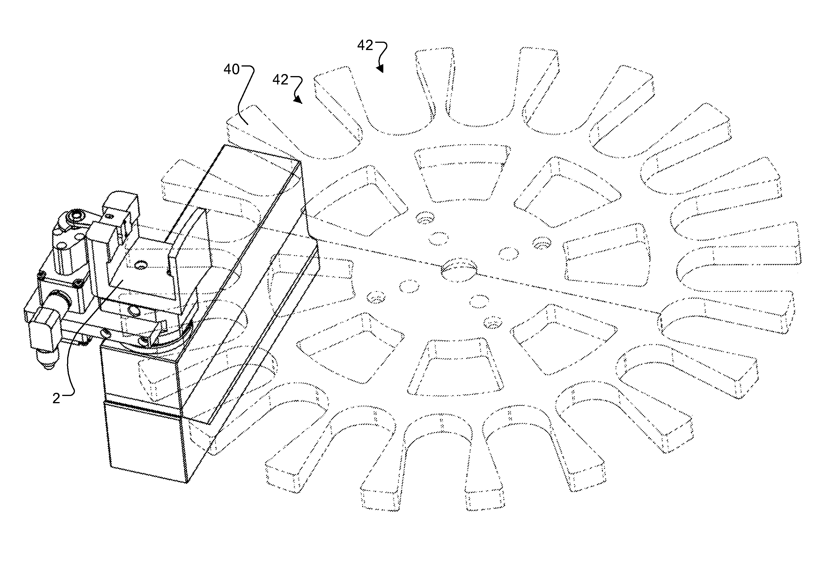
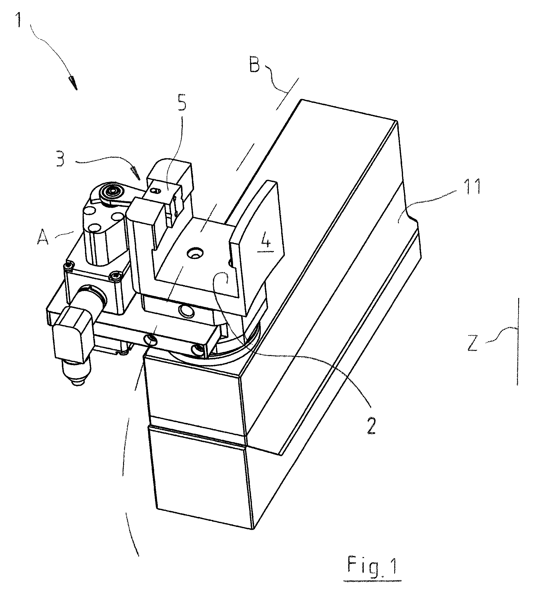
[0030]FIG. 1 shows a weighing system 1. It comprises a weighing cell 11 with a load receiver, not shown in detail, via which the weight to be detected is introduced into the weighing cell and processed there. A weighing table 2 having a substantially U-shaped design in a side view rests on the load receiver. A transport path B for containers to be weighed, not shown in detail, runs across weighing table 2, the containers being conveyed at least at a lower section between the two legs of the U-shaped weighing table 2. The conveyance path B is circular in shape and thus corresponds to the path of a star wheel about a schematically indicated vertical axis Z.

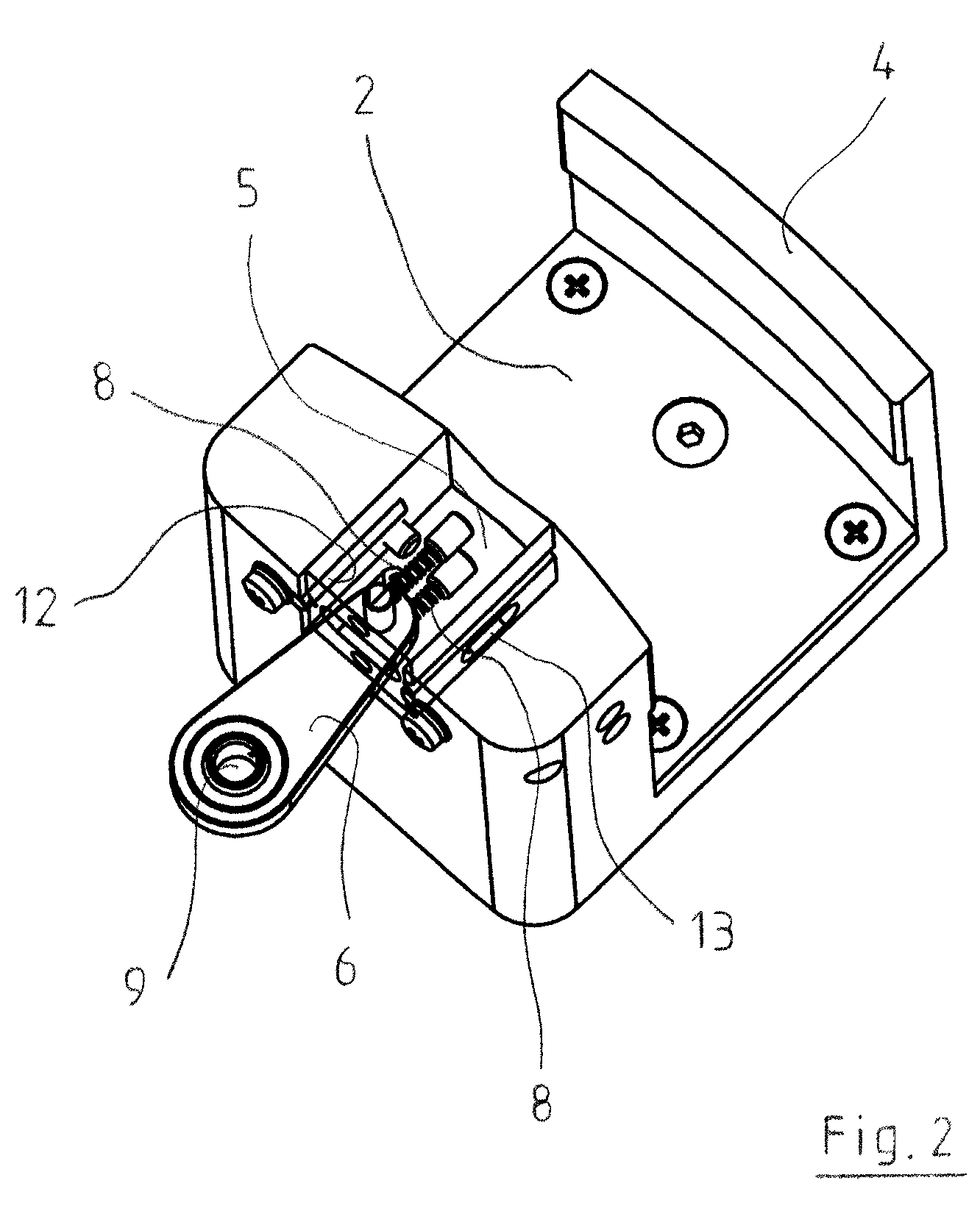
[0031]A clamping device 3 formed on weighing system 1 serves for temporary fixation of the item to be weighed on the weighing table 2, where the item to be weighed is clamped between a clamping element 5 and a stop 4. Stop 4 is constituted here by one leg of the U-shaped weighing table, while clamping element 5 is guided in the othe...


PUM

PropertyMeasurementUnit
weightaaaaaaaaaa
clamping forceaaaaaaaaaa
movementaaaaaaaaaa

Abstract

Weighing system for weighing sequentially fed items to be weighed, in particular containers, with a weighing table, forming a preload, for receiving the weight of the item to be weighed, wherein the item to be weighed can be fed to the weighing table or removed from the weighing table along a path running across the weighing cell and wherein a clamping device, with which the item to be weighed, after it has been fed to the weighing table and impinges thereon with its weight, can be clamped detachably against a stop of the clamping device to enable being weighed in the clamped state, is provided above the weighing table as a preload.

Description

FIELD OF THE INVENTION[0001]The present invention relates to a weighing system for weighing sequentially fed items to be weighed, in particular, containers.BACKGROUND[0002]Such systems are known in principle from prior art and are used particularly in filling systems. There, containers such as bottles or cans are filled in rapid succession and supplied one after another to a monitoring scale for the filled amount to be determined.[0003]Such a filling device is known from DE 195 13 103 A1. Therein, containers are filled and supplied to at least one star wheel of a scale, to then be conveyed further. The star wheel has individual pockets formed to accommodate the individual containers, so that the containers can be conveyed by contact with the pocket walls and moved onto a circular track.[0004]It proves disadvantageous, in this case, that frictional engagement with the star wheel during weighing must be prevented to determine the filled weight, i.e., the container must be released on ...

Claims


Application Information

Patent Timeline
Patent Type & Authority Patents(United States)
IPC IPC(8): G01G13/00
CPCG01G19/005G01G15/00G01G23/02
Inventor EDRICH, ANDREASMILDENBERGER, STEFAN
Owner WIPOTEC WIEGE UND POSITIONIERSYSTEME GMBH
Why Eureka
Try Eureka