Impeller of multiblade blower and method of manufacuturing the same
a multi-blade blower and blade technology, applied in the direction of non-positive displacement fluid engine components, liquid fuel engine components, circumferential flow pumps, etc., can solve the problems of increased manufacturing man-hours, low rotational strength, and increased manufacturing man-hours, so as to reduce the number of manufacturing man-hours, and reduce the variation of blade position accuracy
- Summary
- Abstract
- Description
- Claims
- Application Information
AI Technical Summary
Benefits of technology
Problems solved by technology
Method used
Image
Examples
modification 1
(6) Modification 1
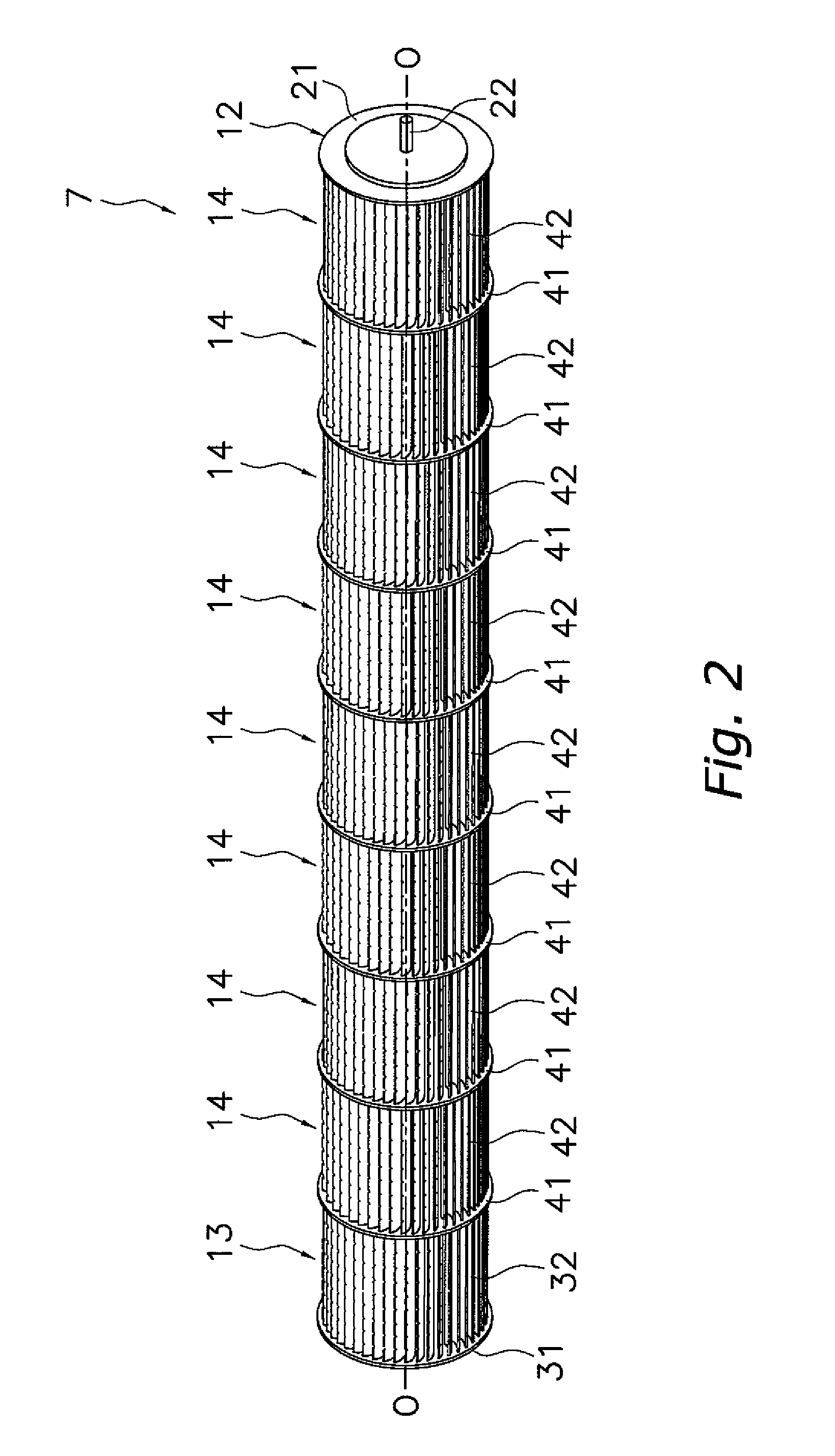
[0093]In the impeller 7 (that is, the first impeller-configuring body 13 and the second impeller-configuring bodies 14) of the preceding embodiment, the step 61 is formed in the rear blade face 51 of each of the blades 32 and 42, but as shown in FIG. 10 and FIG. 11, the step 61 may also be formed in the front blade face 52 of each of the blades 32 and 42. It will be noted that, because the shapes of the blades 32 and 42 are the same as those of the blades 32 and 42 in the preceding embodiment except that the step 61 is formed in the front blade face 52 (thus, the first blade face becomes 52a and the second blade face becomes 52b), description thereof will be omitted here.
[0094]In this case also, similar to the preceding embodiment, effects such as controlling turbulence in the airflow can be obtained.
[0095]Further, a method of manufacturing the impeller 7 (that is, the first impeller-configuring body 13 and the second impeller-configuring bodies 14) where the step ...
modification 2
(7) Modification 2
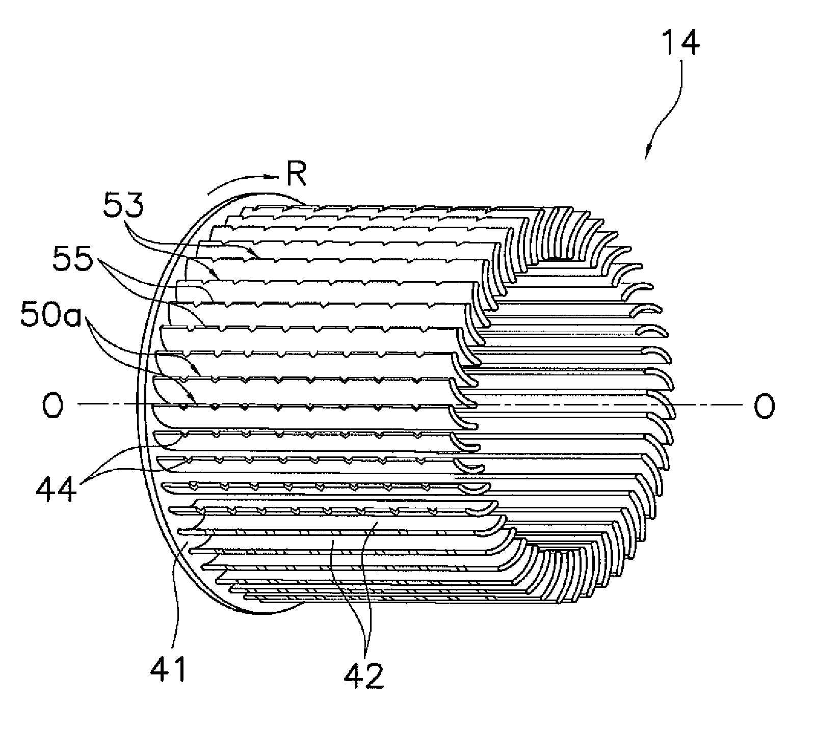
[0113]In the impeller 7 (that is, the first impeller-configuring body 13 and the second impeller-configuring bodies 14) of the preceding embodiment and modification 1, the serrated shape 53 is formed on the outer peripheral blade tip 50a of each of the blades 32 and 42, but the serrated shape 53 may also be formed on the inner peripheral blade tip 50b of each of the blades 32 and 42.
[0114]To describe this using the second impeller-configuring bodies 14 as an example, as shown in FIG. 15, the serrated shape 53 can be formed on the inner peripheral blade tip 50b of each of the blades 42.
[0115]When the second impeller-configuring body 14 is injection-molded, the outer peripheral portions of the blades 42 (specifically, the portions excluding portions to positions a predetermined distance (e.g., the distance σ) from the inner peripheral blade tips 50b of the blades 42) are formed by the second axial-direction-removable mold 181, and the radial-direction-removable molds...
modification 3
(8) Modification 3
[0122]In the impeller 7 (that is, the first impeller-configuring body 13 and the second impeller-configuring bodies 14) of the preceding embodiment and modifications 1 and 2, the cutout portions 54 and the smooth portions 55 configuring the serrated shapes 53 formed on the blade tips of the blades 32 and 42 were alternately disposed in the longitudinal direction of the blades 32 and 42, but as shown in FIG. 17, for example, the serrated shapes 53 may also have a structure comprising just the cutout portions 54 (that is, such that the serrated shapes do not include the smooth portions 55 between the cutout portions 54 in the longitudinal direction).
(9) Other Embodiments
[0123]Embodiments of the present invention have been described above on the basis of the drawings, but the specific configuration thereof is not limited to these embodiments and is alterable in a range that does not depart from the gist of the invention.
PUM
 Abstract
Description
Claims
Application Information
 - R&D
- Intellectual Property
- Life Sciences
- Materials
- Tech Scout
- Unparalleled Data Quality
- Higher Quality Content
- 60% Fewer Hallucinations
Browse by: Latest US Patents, China's latest patents, Technical Efficacy Thesaurus, Application Domain, Technology Topic, Popular Technical Reports.
© 2025 PatSnap. All rights reserved.Legal|Privacy policy|Modern Slavery Act Transparency Statement|Sitemap|About US| Contact US: help@patsnap.com


