Power-aware debugging

a technology of power-aware debugging and integrated circuits, applied in the direction of cad circuit design, program control, instruments, etc., can solve the problems of hdl lack of power management capability, difficult and time-consuming for a designer to debug an hdl design having an associated pdml power-aware, and the role of leakage power consumption has begun to play a more critical role in power consumption

Active Publication Date: 2012-05-08
SYNOPSYS INC
View PDF7 Cites 14 Cited by
  • Summary
  • Abstract
  • Description
  • Claims
  • Application Information

AI Technical Summary

Problems solved by technology

However, as manufacturing processes continue to advance, leakage power consumption has begun to play a more critical role in power consumption.
Since adding power gating, multi-voltage domains or dynamic voltage and frequency scaling late in the design process, at a low gate level of abstraction, can introduce unanticipated bugs in the design, an IC designer should try to plan power management at the register-transfer-level (RTL) or earlier architecture stage of the IC design process.
Although designers typically employ a hardware description language (HDL) to describe an IC design, HDL lacks the capability to model power management.
Even though a simulator can take into account the power intent of a PDML when simulating IC behavior, it can be difficult and time-consuming for a designer to debug an HDL design having associated PDML power-intent.
Debugging an HDL / PDML design can therefore be tedious and error-prone, particularly when the HDL and PDML aspects of a design are developed by different design teams at different stages of the design process.

Method used


Image

  • Power-aware debugging
  • Power-aware debugging
  • Power-aware debugging

Examples


Embodiment Construction

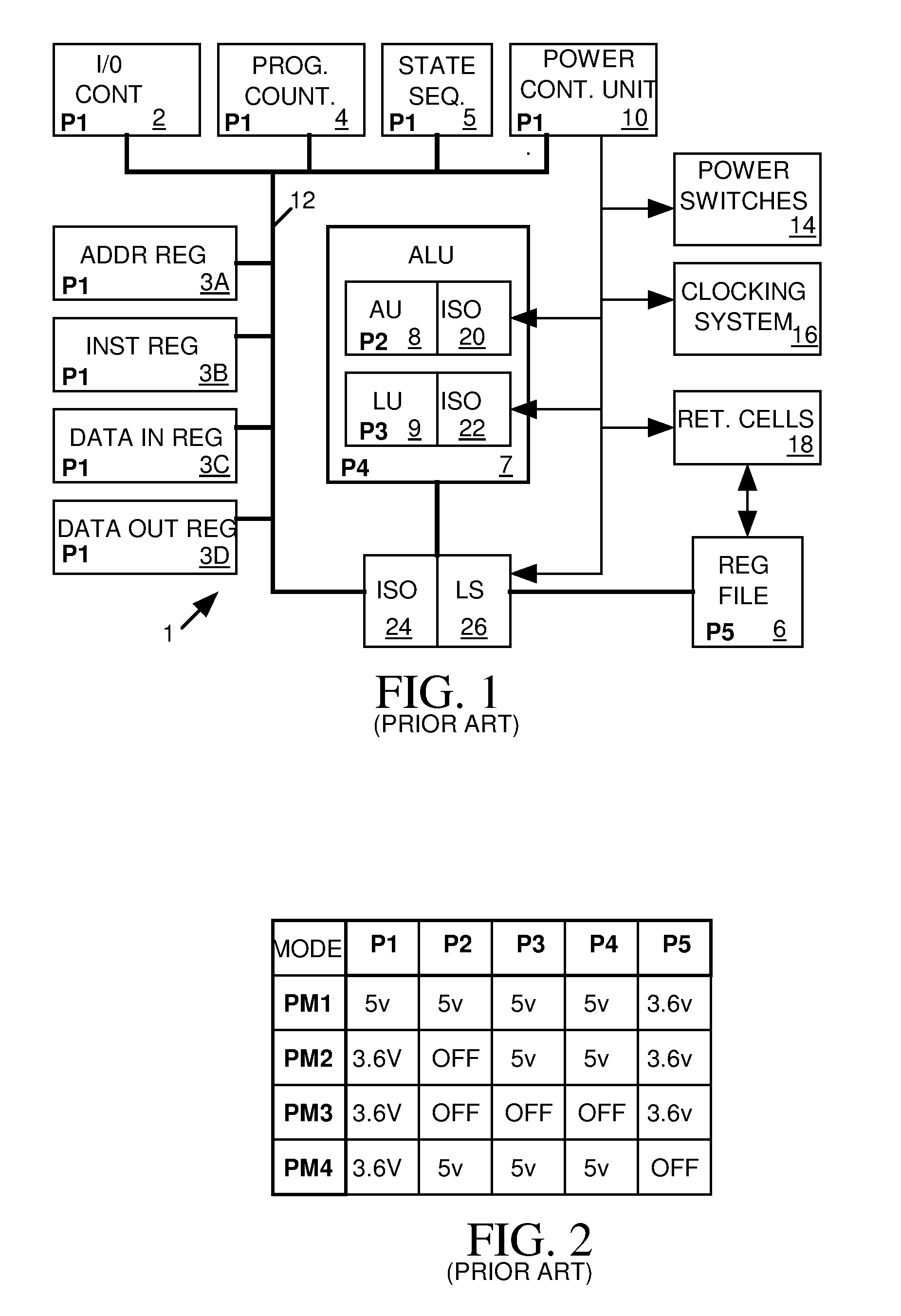
[0033]An IC design may include a power management system to help the IC conserve power. FIG. 1 is a block diagram of an example RISC processor IC 1 including an I / O controller 2, a set of data, address and instruction registers 3A-3D, a program counter 4, a state sequencer 5, a register file unit 6 and an arithmetic logic unit (ALU) 7 and a power control unit 10 that communicate through a bus 12. ALU 7 includes an arithmetic unit (AU) 8 and a logical unit (LU) 9. A set of power switches 14 couple the devices to various power sources and a clocking system 16 supplies clock signals to the various devices for controlling their frequency of operation. As discussed below, power control unit 10 controls various power management features of IC 1.

Power Domains, Power Gating

[0034]A “power domain” (also known as a “power island”) is a set of devices within an IC that receive power from a common source. An IC may have more than one power domain, and some of the power domains may be gated. The ...


PUM


Abstract

A debugging system produces displays in response to an IC design and results of a logic simulation of IC behavior based on the IC design. The IC design includes a hardware description language (HDL) model of the IC describing the IC as comprising cell instances communicating via data signals and power sources for supplying power to the cell instances. The IC design also includes power definition markup language (PDML) model describing a power intent of the IC design. The debugging system generates displays representing HDL code that are annotated to indicate how the power intent of the IC design described by the PDML model relates to the portion of the HDL model represented by the display. The debugging system also generates signals trace displays indicating how both the logic and power intent of the IC design affect the value of a user-selected signal at a user-selected time during the logic simulation.

Description

CROSS-REFERENCE TO RELATED APPLICATION[0001]This application claims benefit under 35 USC 119(e) of Provisional Application No. 61 / 146,895 filed Jan. 23, 2009, the entire disclosure of which is hereby incorporated by reference herein for all purposes.BACKGROUND OF THE INVENTION[0002]1. Field of the Invention[0003]The invention relates in general to systems for verifying integrated circuit (IC) designs, and in particular to a system for debugging power-aware IC designs.[0004]2. Description of Related Art[0005]An IC that is not designed to conserve power can use up to ten times more power than an IC of similar capability that is designed to conserve power. Low-power design not only increases the battery usage for mobile devices but also improves system reliability and lowers the cost of packaging. Low-power techniques such as clock-gating, gate-optimization, multi-VDD, and multi-threshold have been studied for decades and been proved to be effective at reducing dynamic power consumptio...

Claims


Application Information

Patent Timeline
Patent Type & Authority Patents(United States)
IPC IPC(8): G06F17/50
CPCG06F17/5022G06F2217/78G06F30/33G06F2119/06
Inventor YANG, KAILIU, TAYUNGTSAI, FURSHINGANG, TING SHIHHSU, CHIH NENGZHAO, JUN
Owner SYNOPSYS INC
Why Eureka
Try Eureka