
System and method for radiation therapy imaging and treatment workflow scheduling and optimization

a radiation therapy and workflow optimization technology, applied in the field of radiotherapy systems, can solve the problems of unsatisfactory utilization of the capabilities of the most powerful machines, unnecessarily long treatment sessions, and non-optimal use of machinery

Active Publication Date: 2012-05-08
LAP LASER APPLIKATIONEN
View PDF9 Cites 34 Cited by
  • Summary
  • Abstract
  • Description
  • Claims
  • Application Information

AI Technical Summary

Problems solved by technology

However, full utilization of the capabilities of the most powerful machines have not been fully realized because often the use of complex machinery must be carefully balanced against safety requirements.
Adherence to safety requirements, which, of course, may not be compromised, often results in non-optimal use of machinery, unnecessarily long treatment sessions, and unnecessary expense both from non-optimized use of expensive equipment and from poor utilization of human resources.
However, the protons slow down as they pass through tissue and release a large amount of energy immediately before coming to rest.
However, while such optimization may produce more efficient and effective delivery of radiation to the tumor, the limitations of the equipment, the room setup, and delivery process are not considered.
Furthermore, the order of beams in a plan may not be optimal with respect to treatment time or equipment motions.
Because of the many independent actors involved, it is possible that a given workflow plan for delivery of a treatment plan involves steps that present danger to the patient or the equipment due to collisions between pieces of equipment or between equipment and patient.
Because such situations are unacceptable, RTTs typically ensure safety by completely retracting equipment that may be retracted when other equipment is being positioned or when a patient is re-positioned.
Such conservative measures are not efficient in terms of equipment use and time.
Equipment placement, patient positioning, and patient imaging consume the remaining time of a treatment session.
Treatment planning fails to address duration of treatment sessions in terms of minimizing the time expended on inefficient workflow steps.
This system, however, only provides for qualitative evaluation and visual inspection of different treatment configurations in a treatment plan.
Furthermore, this and other similar systems only model traditional couches and radiotherapy equipment used in photon therapy.
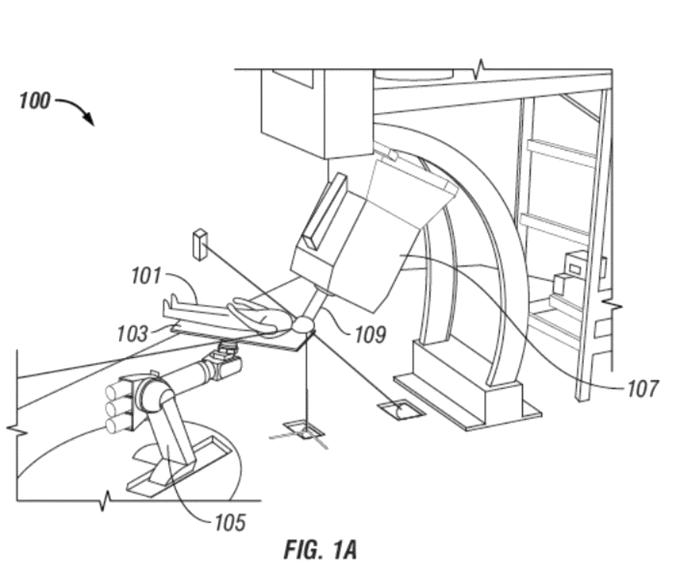
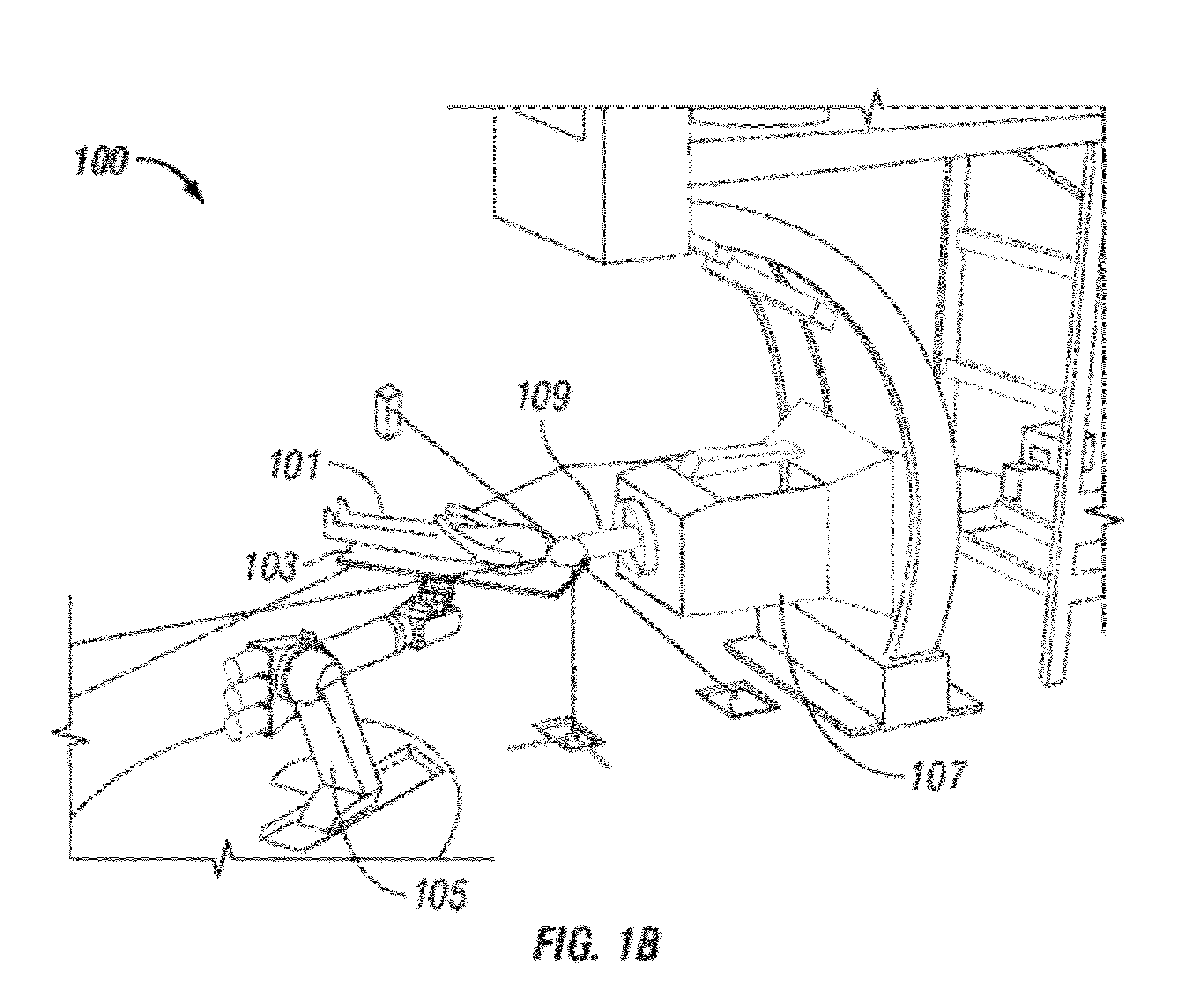
Unlike existing patient positioning couches, robotic couches may execute arbitrarily complex trajectories in 3D space.

Method used


Image

  • System and method for radiation therapy imaging and treatment workflow scheduling and optimization
  • System and method for radiation therapy imaging and treatment workflow scheduling and optimization
  • System and method for radiation therapy imaging and treatment workflow scheduling and optimization

Examples


Embodiment Construction

[0028]In the following detailed description, reference is made to the accompanying drawings that show, by way of illustration, specific embodiments in which the invention may be practiced. These embodiments are described in sufficient detail to enable those skilled in the art to practice the invention. It is to be understood that the various embodiments of the invention, although different, are not necessarily mutually exclusive. For example, a particular feature, structure, or characteristic described herein in connection with one embodiment may be implemented within other embodiments without departing from the spirit and scope of the invention. In addition, it is to be understood that the location or arrangement of individual elements within each disclosed embodiment may be modified without departing from the spirit and scope of the invention. The following detailed description is, therefore, not to be taken in a limiting sense, and the scope of the present invention is defined on...


PUM


Abstract

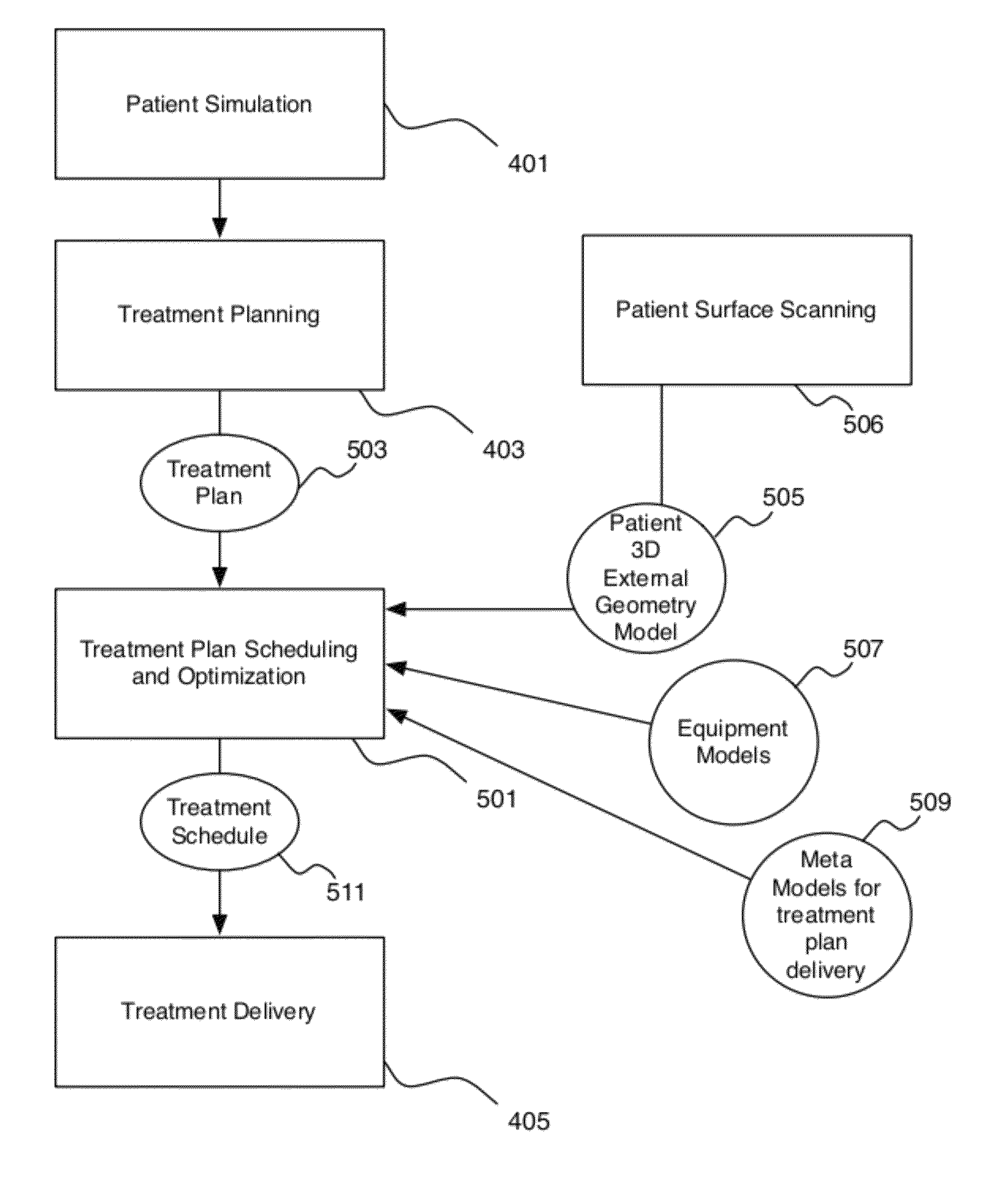
External beam radiotherapy treatment workflow scheduling and optimization. The system and method provides for determining a workflow metamodel, receiving a treatment plan, determining a treatment schedule corresponding to the workflow metamodel and treatment plan, taking into account safety by determining alternative treatment schedules, computing a safety index, and selecting one alternative treatment schedule that satisfies a safety threshold and that provides an optimal schedule.

Description

BACKGROUND OF THE INVENTION[0001]The present invention relates generally to radiotherapy systems, and more particularly to schedule optimization for delivery of external beam radiotherapy treatment.[0002]Advances in technology have led to great progress in the treatment of many diseases. However, full utilization of the capabilities of the most powerful machines have not been fully realized because often the use of complex machinery must be carefully balanced against safety requirements. Adherence to safety requirements, which, of course, may not be compromised, often results in non-optimal use of machinery, unnecessarily long treatment sessions, and unnecessary expense both from non-optimized use of expensive equipment and from poor utilization of human resources.[0003]The foregoing may be more true for radiation oncology than for any other medical field in that radiation oncology has been driven more by technological innovation involving complex, expensive and potentially hazardou...

Claims


Application Information

Patent Timeline
Patent Type & Authority Patents(United States)
IPC IPC(8): G06Q50/00A61N5/00
CPCA61N5/1048G06F19/327A61B6/4458G06F19/3481G06Q10/0633G06Q50/22A61N5/103G06F19/3437A61N5/1081G16H20/40G16H40/20G16H50/50
Inventor KAPOOR, CHETANJUNG, EDWIN
Owner LAP LASER APPLIKATIONEN
Learn More