
Seat occupancy verification system for motor vehicles

Inactive Publication Date: 2012-05-01
LORS JEAN PIERRE
View PDF9 Cites 23 Cited by
  • Summary
  • Abstract
  • Description
  • Claims
  • Application Information

AI Technical Summary

Benefits of technology

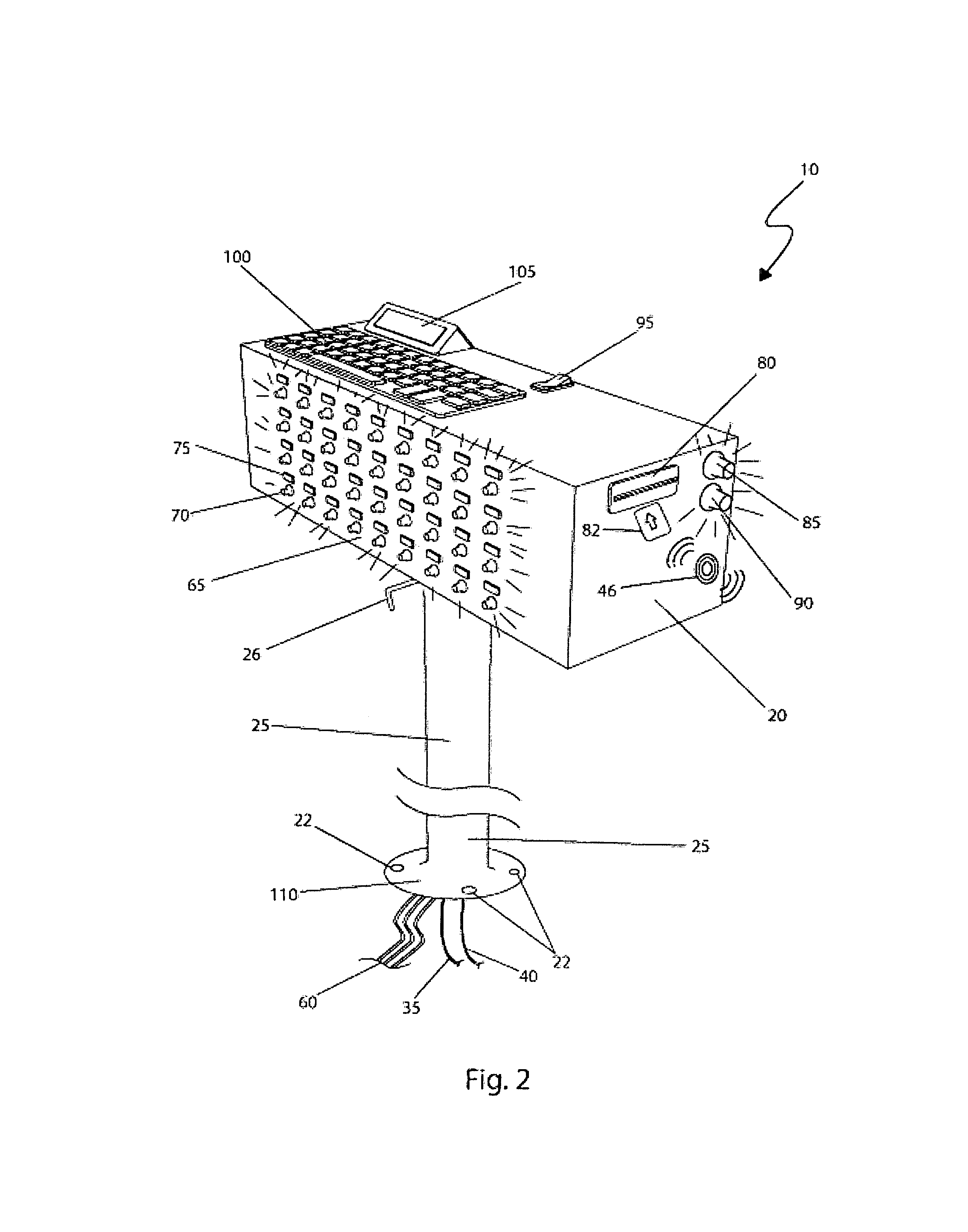
[0017]Yet another object of the seat occupancy verification system provides a main control cabinet that is located adjacent to an operator so that the main control cabinet is easily visible and physically accessible to the operator.
[0020]Still a further object of the seat occupancy verification system is a quick-release mechanism that permits the main control cabinet to be rotationally pivoted by an operator to a desired position.
[0021]Yet still another object of the seat occupancy system is that the quick-release mechanism further permits the main control cabinet to be easily removed and placed in another vehicle or in another location if so desired.
[0022]Still another object of the seat occupancy system is that the electrical connections to the main control cabinet may be easily connected or disconnected through the use of dedicated connectors so that the main control cabinet may be easily disconnected form the system.
[0028]Yet another aspect of the seat occupancy verification system comprises a first connector, a second connector, and an extension cable that provide convenient electrical connection and disconnection of the main control cabinet to the system, thereby allowing removal of the control cabinet from the system.

Problems solved by technology

When children are overlooked in conveyances of this sort, it may have dreadful consequences.
However in some cases, such as in inclement weather, weekends, or when a parent thinks the child is with someone else, the event can end tragically with a child's death.
The causes of such oversight are many and may include new bus drivers, substitute bus drivers, or more likely, a child that has simply fallen asleep.
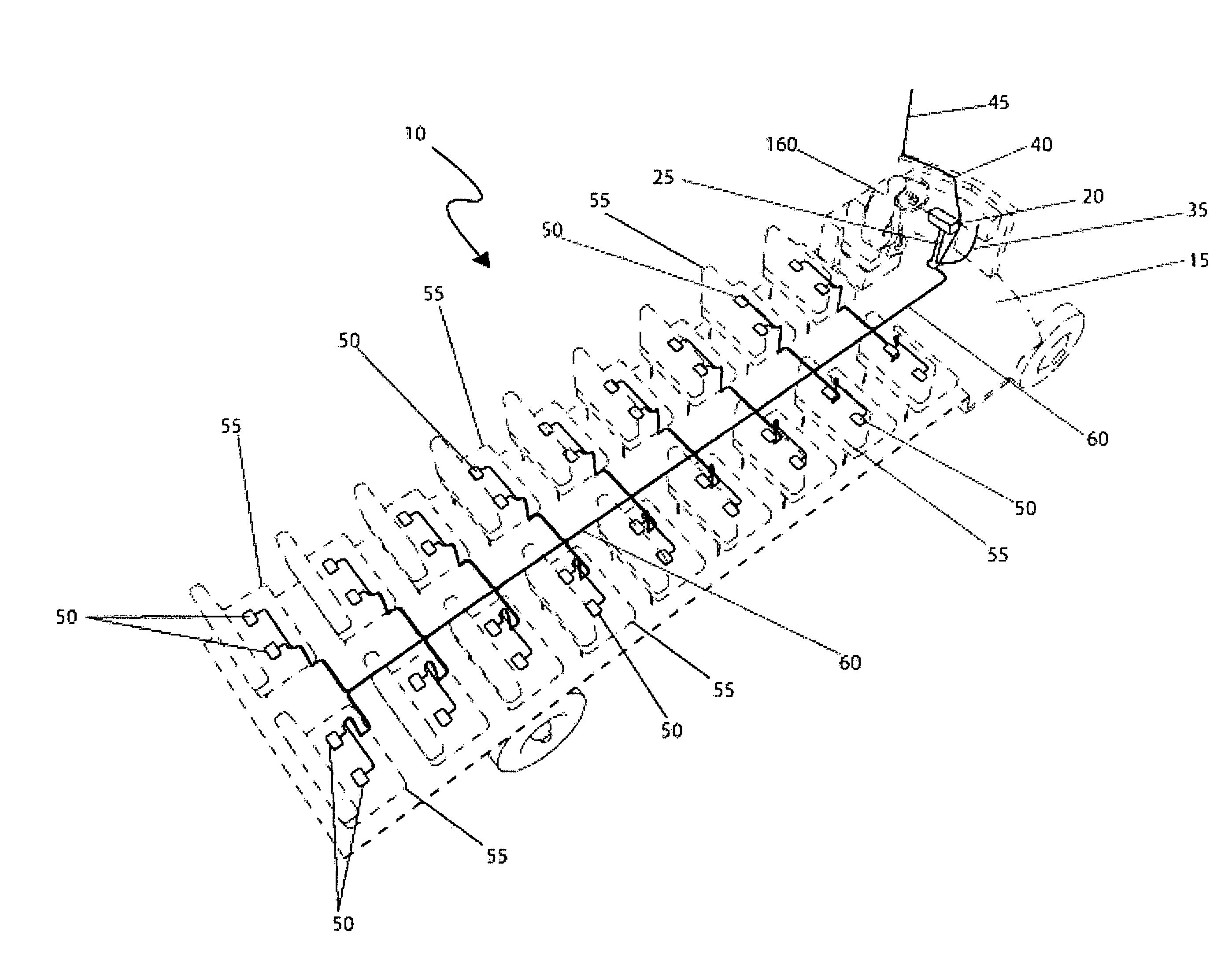
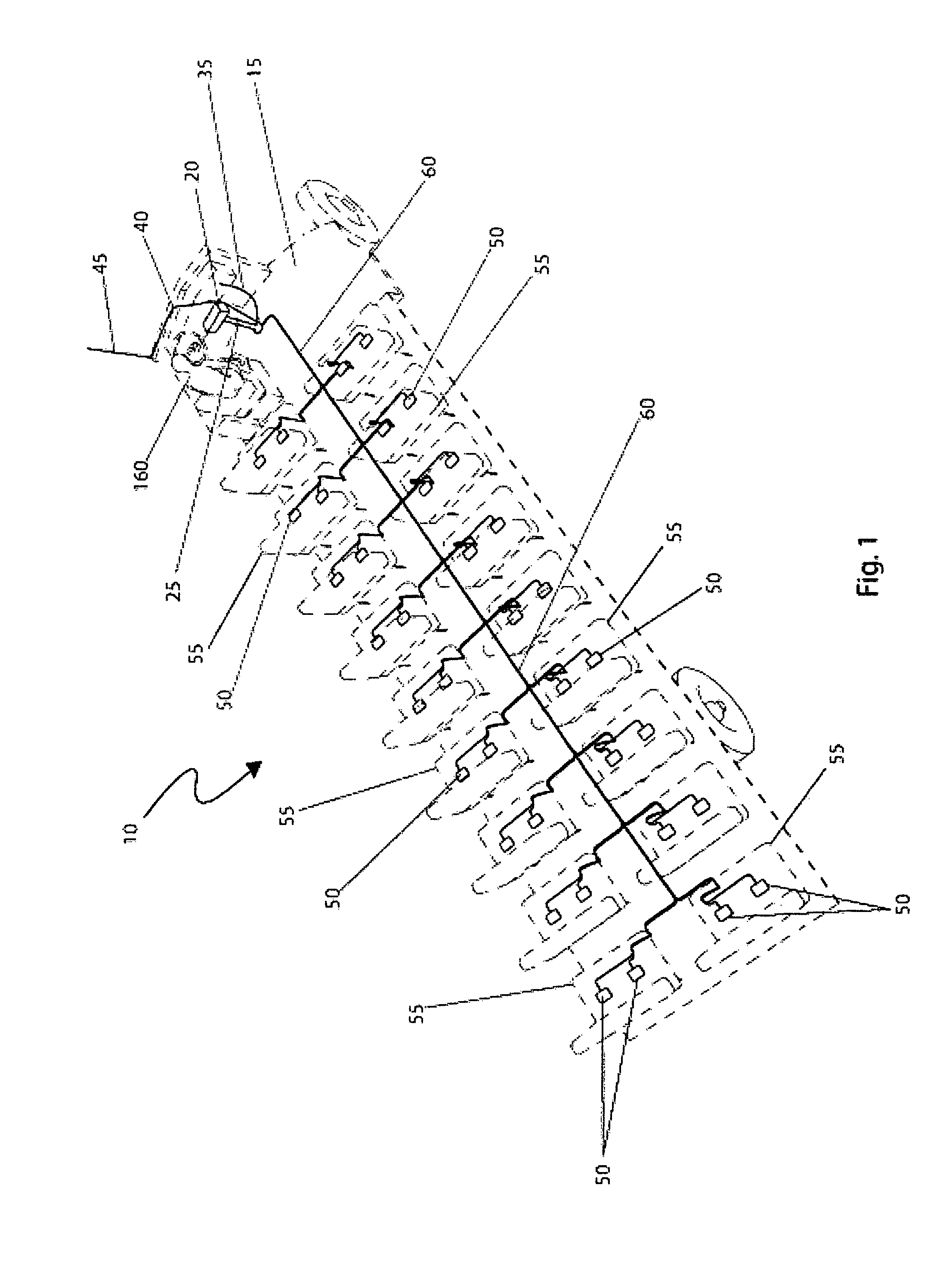
Unfortunately, this patent does not appear to disclose an apparatus and method the uses a unique identifier card issued to school children to monitor a child's presence on a school bus nor does this patent appear to disclose the use of a plurality of sensors located in the seats of a multiple passenger vehicle that electronically communicate with a main control cabinet.
Unfortunately, this patent does not appear to disclose a main control cabinet that is pivotally adjustable adjacent to an operator nor does it appear to disclose the use of unique identifier cards issued to passengers that are read by a reader on the main control cabinet.
Unfortunately, this patent does not appear to a system that utilizes unique identifier cards issued to passengers to determine their presence in an assigned seat on a vehicle nor does this patent appear to disclose a system capable of wireless control and monitoring.
Unfortunately, this patent does not appear to disclose a disclose an apparatus and method the uses a unique identifier card issued to school children to monitor a child's presence on a school bus nor does this patent appear to disclose the use of a plurality of sensors located in the seats of a multiple passenger vehicle that electronically communicate with a main control cabinet.
Unfortunately, this patent does not appear to disclose an apparatus that is utilized to detect the presence of a child on a multiple passenger vehicle and that is capable of alerting responsible individuals of that situation.
Unfortunately, this patent does not appear to a system that utilizes unique identifier cards issued to passengers to determine their presence in an assigned seat on a vehicle nor does this patent appear to disclose a system capable of wireless control and monitoring.
Unfortunately, this patent does not appear to disclose a sensing system for children capable of detecting the presence of a child on a multiple passenger vehicle and that further alerts individuals to the unattended child nor does it appear that this system is capable of wireless control and monitoring via an external antenna.

Method used


Image

  • Seat occupancy verification system for motor vehicles
  • Seat occupancy verification system for motor vehicles
  • Seat occupancy verification system for motor vehicles

Examples


Embodiment Construction

[0037]The best mode for carrying out the invention is presented in terms of its preferred embodiment, herein depicted within FIGS. 1 through 4. However, the invention is not limited to the described embodiment, and a person skilled in the art will appreciate that many other embodiments of the invention are possible without deviating from the basic concept of the invention, and that any such work around will also fall under scope of this invention. It is envisioned that other styles and configurations of the present invention can be easily incorporated into the teachings of the present invention, and only one particular configuration shall be shown and described for purposes of clarity and disclosure and not by way of limitation of scope.

[0038]The terms “a” and “an” herein do not denote a limitation of quantity, but rather denote the presence of at least one of the referenced items.

[0039]The present invention describes a system and method for a seat occupancy verification system for ...


PUM


Abstract

A system and methodology utilizing seat sensors and an electronic card system that monitors the location of children on a bus as well as preventing children from being left behind, is herein disclosed. As the child enters the bus, the child would insert a personalized identification card, thereby recording the child's seat location and presence. Upon exiting, the child again inserts the identification card and following a prescribed time interval, a warning light and alarm would be activated if the seat remains occupied, thus alerting the bus driver to check the seat location. Every bus seat would have an integral weight sensor electrically connected to a main control panel. The system provides the bus driver, or assigned chaperone, a pushbutton selection array corresponding to each seat assignment.

Description

RELATED APPLICATIONS[0001]The present invention was first described in and claims the benefit of U.S. Provisional Patent Application No. 60 / 967,982 filed on Sep. 10, 2007, the entire disclosures of which are incorporated herein by reference.FIELD OF THE INVENTION[0002]The present invention relates generally to a tobacco product filtration device and, more particularly, to said device reducing second hand smoke.BACKGROUND OF THE INVENTION[0003]There are many situations where children require transportation on multiple passenger vehicles. Field trips and transportation to school require a school bus. Some children are transported in large multiple passenger vans. Airplanes, commercial buses, trains all create situations where children can be easily displaced or forgotten about due to other pressures on a vehicle operator. When children are overlooked in conveyances of this sort, it may have dreadful consequences. Children have died from being left in overheated vehicles. Accordingly, ...

Claims


Application Information

Patent Timeline
IPC IPC(8): G08B21/22
CPCB60N2/002B60N2/242G08B21/22
Inventor LORS, JEAN-PIERRE
Owner LORS JEAN PIERRE
Learn More