Contact device for a high resistive power contactor

a contact device and high resistive power technology, applied in the field of contact systems, to achieve the effect of reducing heat rise and cost and increasing the operating scop

Active Publication Date: 2012-04-24
SCHNEIDER ELECTRIC IND SAS
View PDF10 Cites 2 Cited by
  • Summary
  • Abstract
  • Description
  • Claims
  • Application Information

AI Technical Summary

Benefits of technology

[0007]According to one aspect, the invention thus relates to a contact device comprising a substantially flat and preferably rectangular connection terminal strip, wherein holes are drilled for connecting electric power supply bars, said terminal strip being extended by several conductors, preferably folded into a U, which comprise stationary contact areas. The final architecture of the contactor thereby makes the phase connections easier to see, each of these connections being associated with a single incoming, respectively outgoing, device and therefore only comprising a single connection strip on input, respectively on output. Connection errors are thereby prevented.
[0011]The first branch of each conductor can comprise holes for securing the pieces of the contact device in a case, the conductors then advantageously being parallel to one another. The connection parts of each piece also comprise holes that are superposed when the devices according to the invention are assembled so that connection of the power supply bars achieves securing of the connection parts on one another and optimizes electrical conduction. For the contact to be homogeneous, it is advantageous to fit four bolts on the connection surface.

Problems solved by technology

AC1 contactors over 1500 A are thus conventionally based on the technology referred to as “contactor on bar”, very bulky and made to measure, thereby being costly.

Method used


Image

  • Contact device for a high resistive power contactor
  • Contact device for a high resistive power contactor
  • Contact device for a high resistive power contactor

Examples


Embodiment Construction

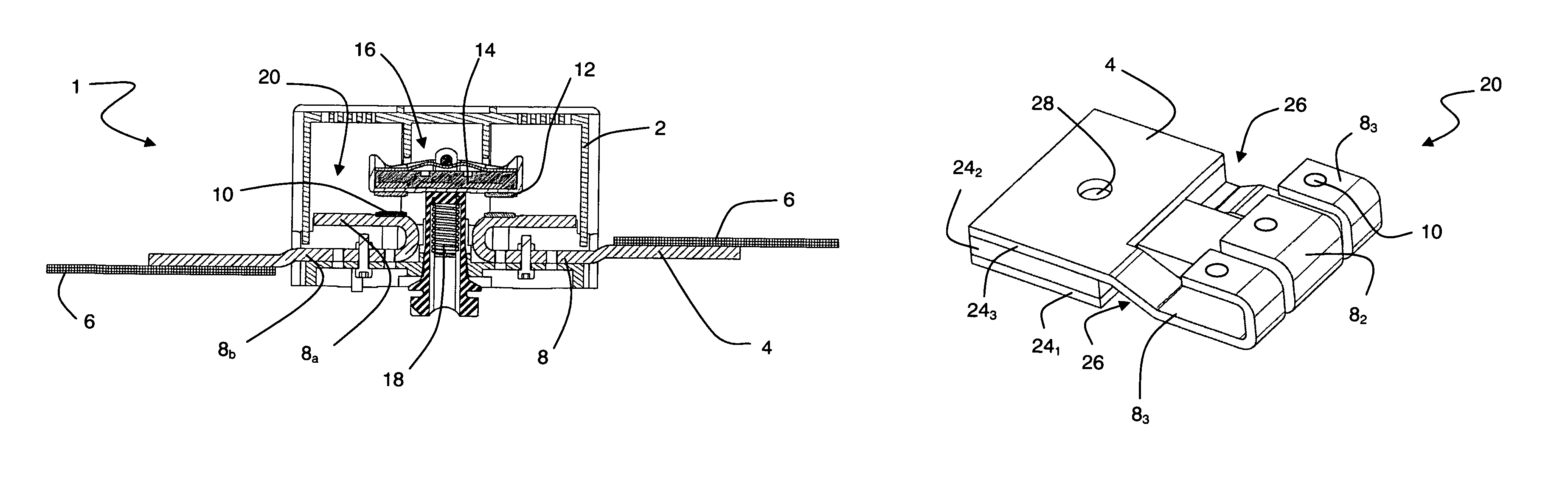
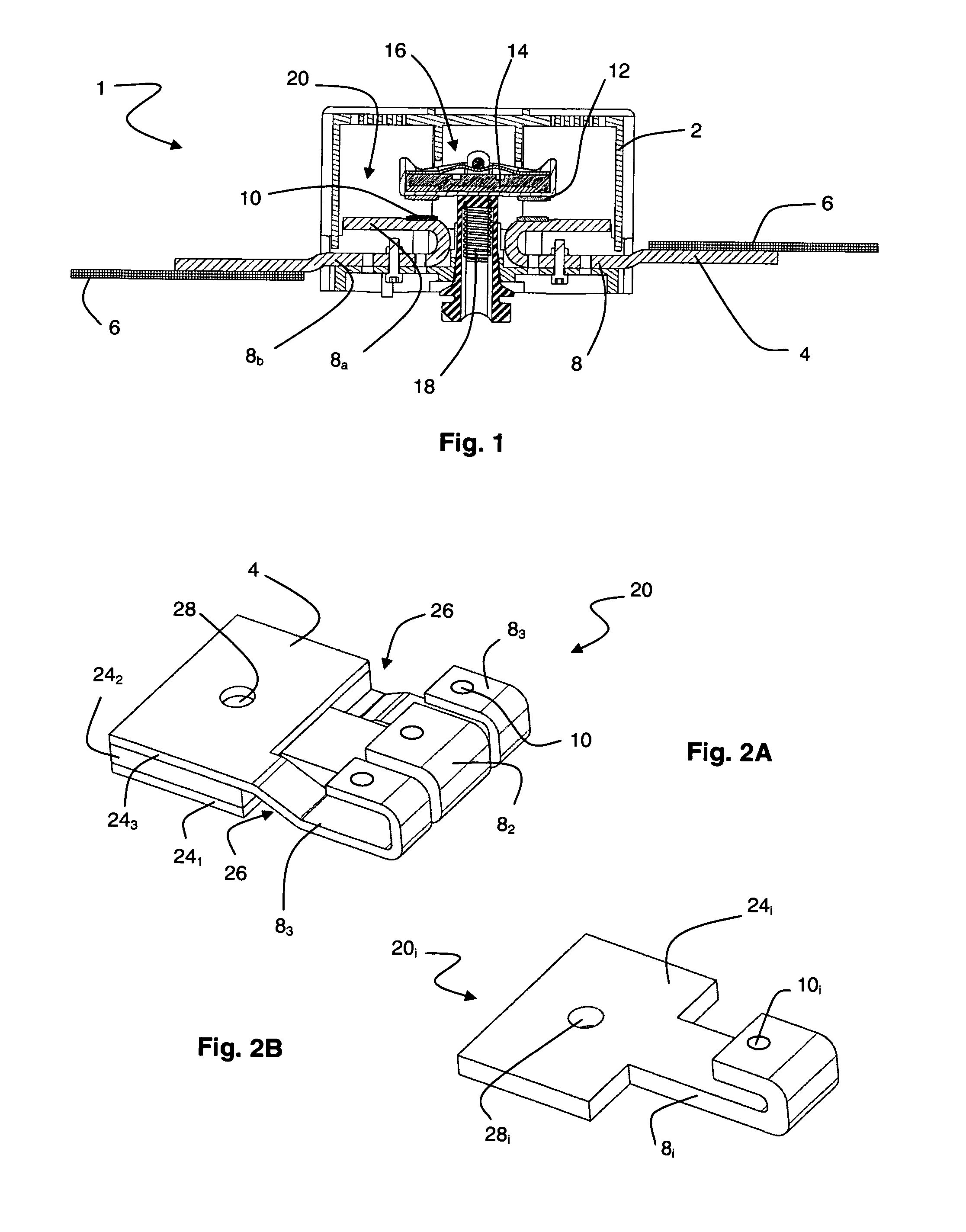
[0017]The invention finds a particular and preferred application in a contactor 1 with a molded case 2 used in three-phase power supply. For each of the phases, contactor 1 comprises a conduction circuit as illustrated schematically in FIG. 1, the circuits being juxtaposed normally in the drawn plane (of the sheet), for example inside the same case 2.

[0018]In particular, according to a conventional construction, for each supply phase, two connection terminal strips 4 are protruding from case 2 of contactor 1 and are designed to be connected to a set of supply bars 6. Connection terminal strips 4 are extended inside case 2 by conductors 8 comprising two stationary contact areas 10 separated from one another. Contact areas 10 can, depending on the uses, either be manufactured unitarily with conductor 8 itself or be added on, with for example brazing of pads on a support arranged in conductor 8. Two contacts 12 coupled by a conductor 14 are located facing stationary contacts 10 and for...


PUM


Abstract

A contactor comprises, for each phase, a pair of contact devices which comprise a connection strip and at least two conductors provided with a stationary contact, and a movable contact bridge able to close the two stationary contacts or not. According to the invention, the contact device is formed from superposition of a number of pieces equal to the number of conductors, each piece comprising one of the conductors and a connection part corresponding to the connection strip but of smaller thickness. Each of the pieces can be made from folded metal. The connection parts are coupled to one another to form the connection strip by means of holes at the same time as the sets of bars are secured thereto.

Description

TECHNICAL FIELD[0001]The invention relates to contact systems of electrical breaking and switching equipment, in particular contactors. The invention relates more particularly to the contact device extending between the connection terminal strip and the stationary contact area of such equipment, in particular in the case of use for high resistive power loads.STATE OF THE ART[0002]A contactor is a switching device with electric or pneumatic control the function of which is similar to that of an electromechanical relay, i.e. making or breaking the flow of current. This electrical engineering equipment with a high breaking capacity is in particular used to supply industrial motors with a power of more than 0.5 kW, and can withstand a higher current than the relay. Standardized categories of use, depending on the nature of the receiver and on the conditions in which closing and opening take place, fix the current values that the contactor has to withstand. For example, the AC3 category ...

Claims


Application Information

Patent Timeline
Patent Type & Authority Patents(United States)
IPC IPC(8): H01H1/06
CPCH01H50/14H01H9/40H01H50/546
Inventor LARCHER, PATRICKGUIBERT, JULIENREBOULET, JOEL
Owner SCHNEIDER ELECTRIC IND SAS
Why Eureka
Try Eureka