
Mechanism for converting rotational motion into linear motion

a technology of rotational motion and conversion mechanism, which is applied in the direction of belt/chain/gearing, toothed gearing, belt/chain/gearing, etc., can solve the problems of reducing the conversion efficiency of rotational motion into linear motion, increasing local wear, etc., and reducing the life of the conversion mechanism. , the effect of suppressing the inclination of the planetary shaft 4

Active Publication Date: 2012-04-24
TOYOTA JIDOSHA KK +1
View PDF24 Cites 5 Cited by
  • Summary
  • Abstract
  • Description
  • Claims
  • Application Information

AI Technical Summary

Benefits of technology

[0005]Accordingly, it is an objective of the present invention to provide a rotation / linear motion conversion mechanism that suppresses inclination of planetary shafts caused by engagement of gears of the planetary shafts and a gear of at least one of a annular shaft and a sun shaft.

Problems solved by technology

This increases local wear, thus reducing the conversion efficiency of rotational motion into linear motion.
Such a problem occurs not only in the above conversion mechanism but in any conversion mechanism including gear mechanisms configured by the gears of the planetary shafts and the gear of at least one of the annular shaft and the sun shaft.

Method used


Image

  • Mechanism for converting rotational motion into linear motion
  • Mechanism for converting rotational motion into linear motion
  • Mechanism for converting rotational motion into linear motion

Examples


example 3

SETTING EXAMPLE 3

[0148](A) Motion converting mode: “sun shaft displacement mode”

[0149](B) Relationship of sun / planetary threaded portions: “forward direction”

[0150](C) Number of planetary shafts: “9”

[0151](D) Number of threads ratio of threaded portions: “−5:1:5”

[0152](E) Number of teeth ratio of gears: “31:10:50”

[0153](F) Effective diameter ratio of threaded portions: “3:1:5”

[0154](G) Effective diameter ratio of gears: “3.1:1:50”

[0155](H) Number of effective threads: “−8”

[0156](I) Number of effective teeth: “1”

example 4

SETTING EXAMPLE 4

[0157](A) Motion converting mode: “sun shaft displacement mode”

[0158](B) Relationship of sun / planetary threaded portions: “reverse direction”

[0159](C) Number of planetary shafts: “11”

[0160](D) Number of threads ratio of threaded portions: “5:1:6”

[0161](E) Number of teeth ratio of gears: “39:10:60”

[0162](F) Effective diameter ratio of threaded portions: “4:1:6”

[0163](G) Effective diameter ratio of gears: “3.9:1:6”

[0164](H) Number of effective threads: “1”

[0165](I) Number of effective teeth: “−1”

example 5

SETTING EXAMPLE 5

[0166](A) Motion converting mode: “sun shaft displacement mode”

[0167](B) Relationship of sun / planetary threaded portions: “reverse direction”

[0168](C) Number of planetary shafts: “7”

[0169](D) Number of threads ratio of threaded portions: “2:1:5”

[0170](E) Number of teeth ratio of gears: “25:9:45”

[0171](F) Effective diameter ratio of threaded portions: “3:1:5”

[0172](G) Effective diameter ratio of gears: “2.78:1:5”

[0173](H) Number of effective threads: “−1”

[0174](I) Number of effective teeth: “−2”


PUM


Abstract

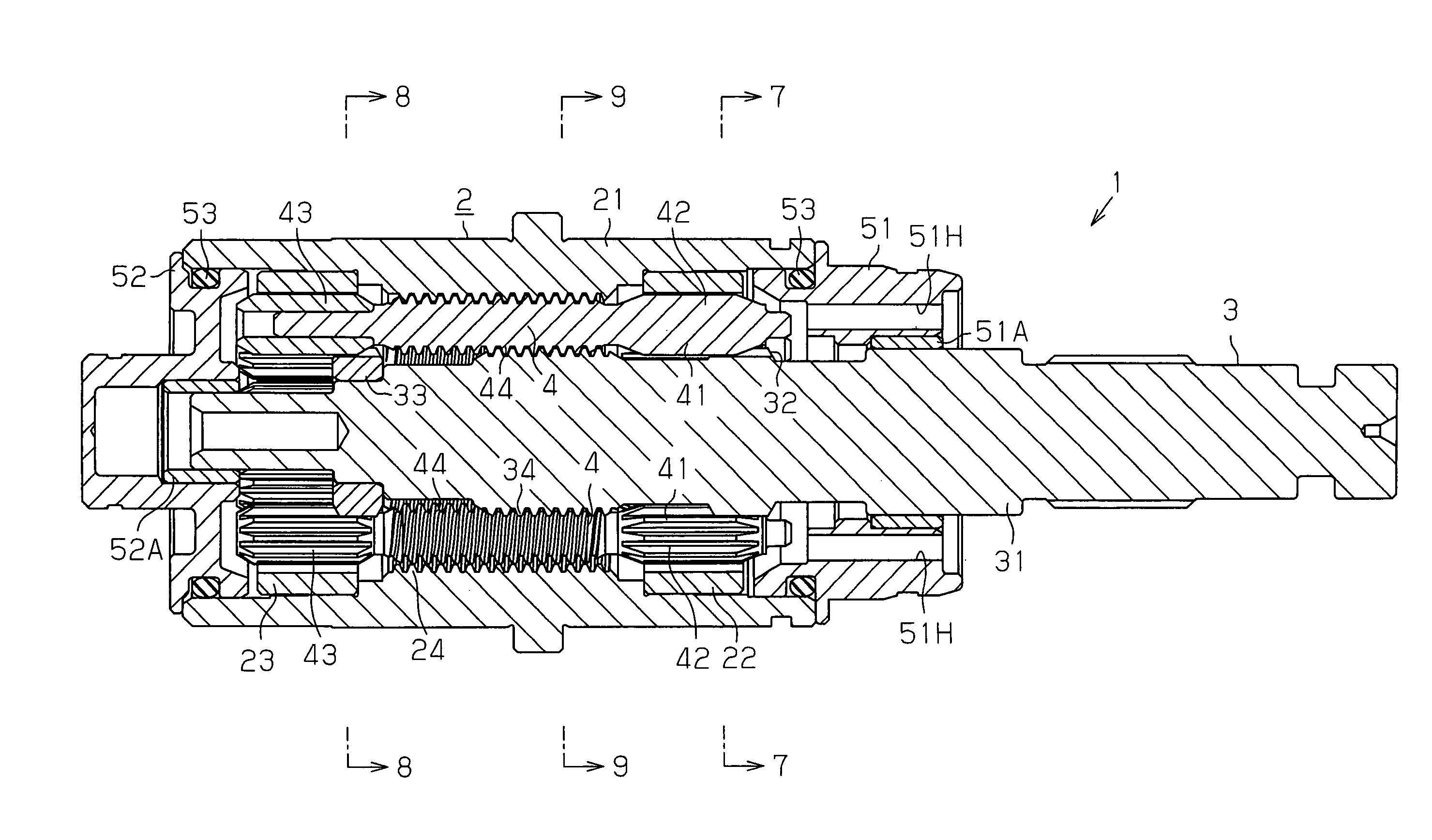
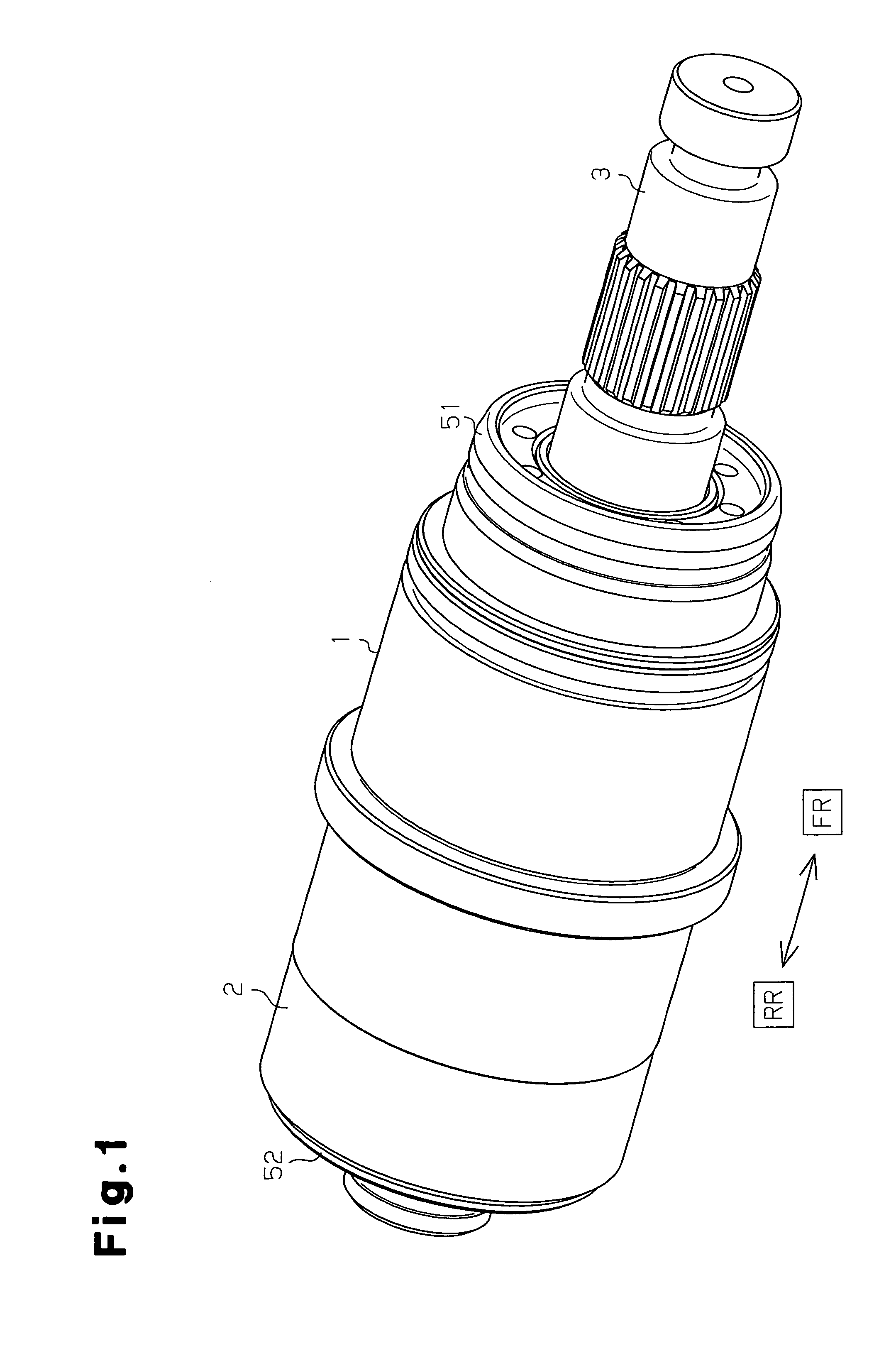
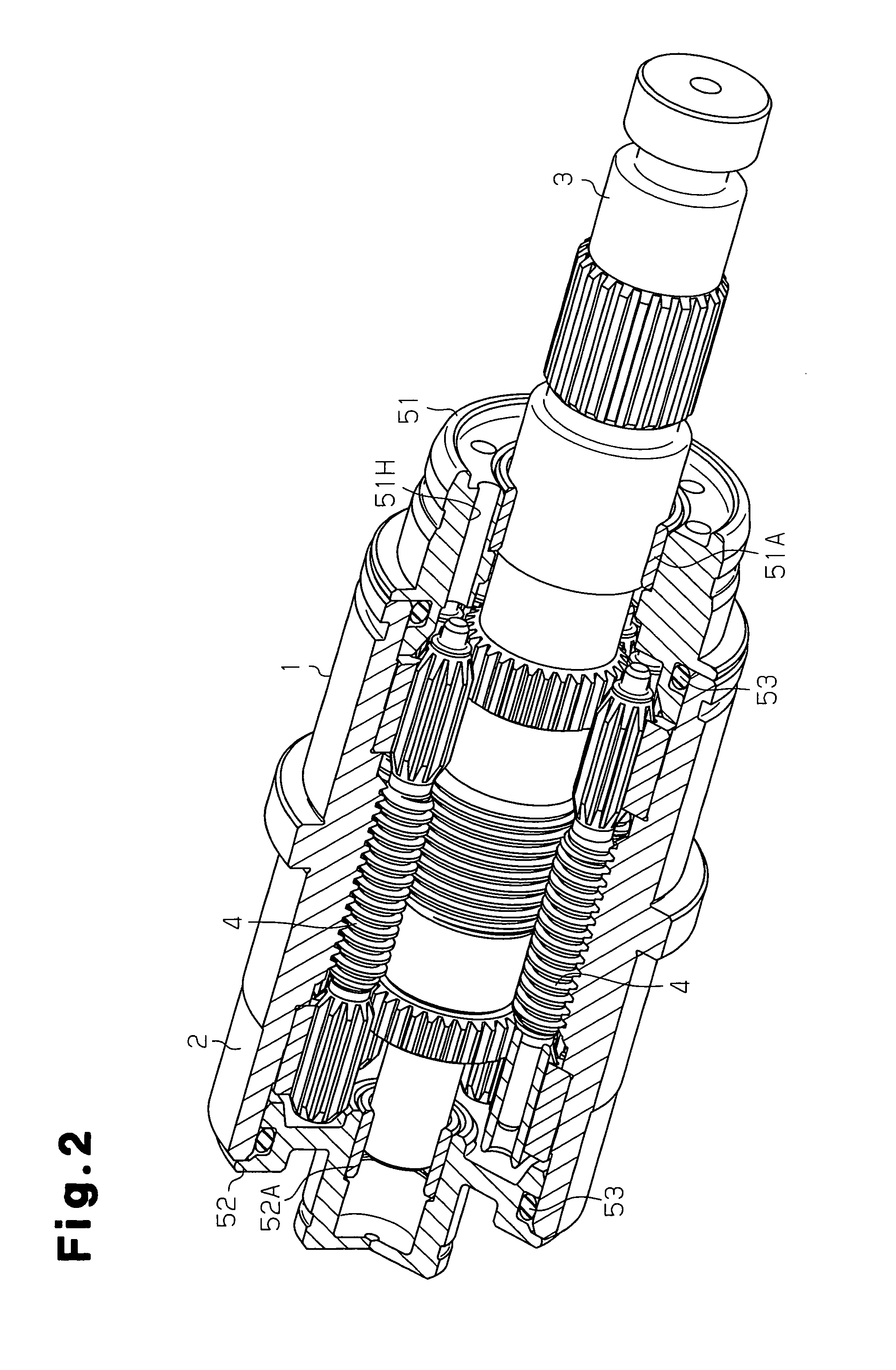
A rotation / linear motion conversion mechanism provided with an annular shaft, a sun shaft arranged inside the annular shaft, planetary shafts arranged around the sun shaft, and a first gear mechanism and a second gear mechanism, which transmit force between the annular shaft and the planetary shafts. Each planetary shaft includes a first planetary gear, which configures part of the first gear mechanism, and a second gear, which configures part of the second gear mechanism. The planetary shaft is configured to permit relative rotation between the first planetary gear and the second planetary gear.

Description

FIELD OF THE INVENTION[0001]The present invention relates to a rotation / linear motion conversion mechanism for converting rotational motion into linear motion.BACKGROUND OF THE INVENTION[0002]As a mechanism for converting rotational motion into linear motion, for example, a conversion mechanism disclosed in Patent Document 1 has been proposed. The conversion mechanism includes a annular shaft, which has a space extending in the axial direction therein, a sun shaft, which is arranged inside the annular shaft, and planetary shafts, which are arranged around the sun shaft. Also, externally thread portions formed on the outer circumference of the planetary shafts are engaged with an internally thread portion formed on the inner circumference of the annular shaft, and an externally threaded portion formed on the outer circumference of the sun shaft. Thus, force is transmitted among these components. Sun-and-planet motion of the planetary shafts that is obtained when the annular shaft is ...

Claims


Application Information

Patent Timeline
Patent Type & Authority Patents(United States)
IPC IPC(8): F16H57/08
CPCF16H25/2252Y10T74/18056Y10T74/18664F16H25/18F16H25/20F16H25/00
Inventor HORI, KOHEIHASHIMOTO, HIROMICHIKINOSHITA, YASUONAKAMURA, KIYOHARUTSUZUKUI, MOTOHIROSATOH, OSAMU
Owner TOYOTA JIDOSHA KK
Learn More