
Door latch device for a motor vehicle

a technology for latching devices and motor vehicles, applied in anti-theft devices, lock applications, doors, etc., can solve problems such as its complicated structur

Inactive Publication Date: 2012-04-10
MITSUI KINZOKU ACT
View PDF15 Cites 23 Cited by
  • Summary
  • Abstract
  • Description
  • Claims
  • Application Information

AI Technical Summary

Benefits of technology

This design results in a more compact and simplified door latch device with reduced parts, enhancing the stability and efficiency of the operating mechanism while maintaining secure locking and unlocking functions.

Problems solved by technology

With increase in the number of other parts, there are a lot of parts for coupling each element to each other at an operating-force transmitting path between the motor and the interconnecting lever, thereby making its structure more complicated.

Method used


Image

  • Door latch device for a motor vehicle
  • Door latch device for a motor vehicle
  • Door latch device for a motor vehicle

Examples


Embodiment Construction

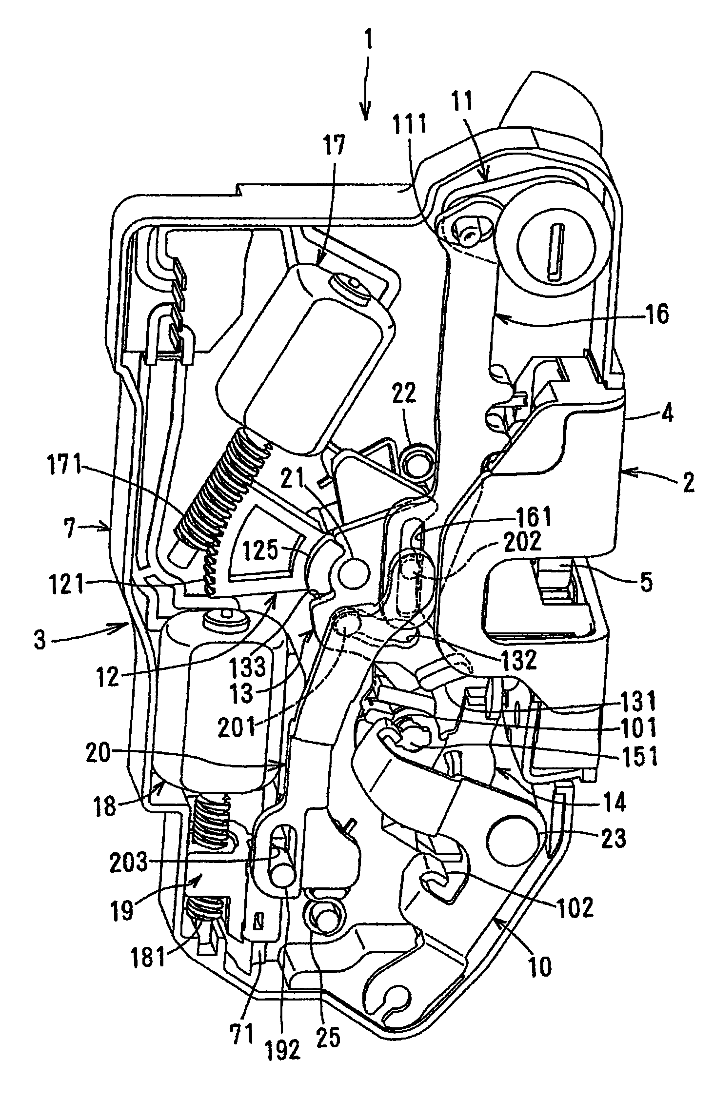
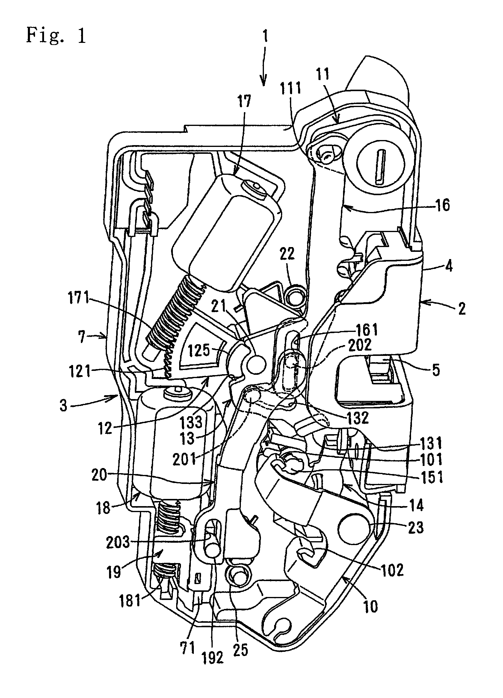
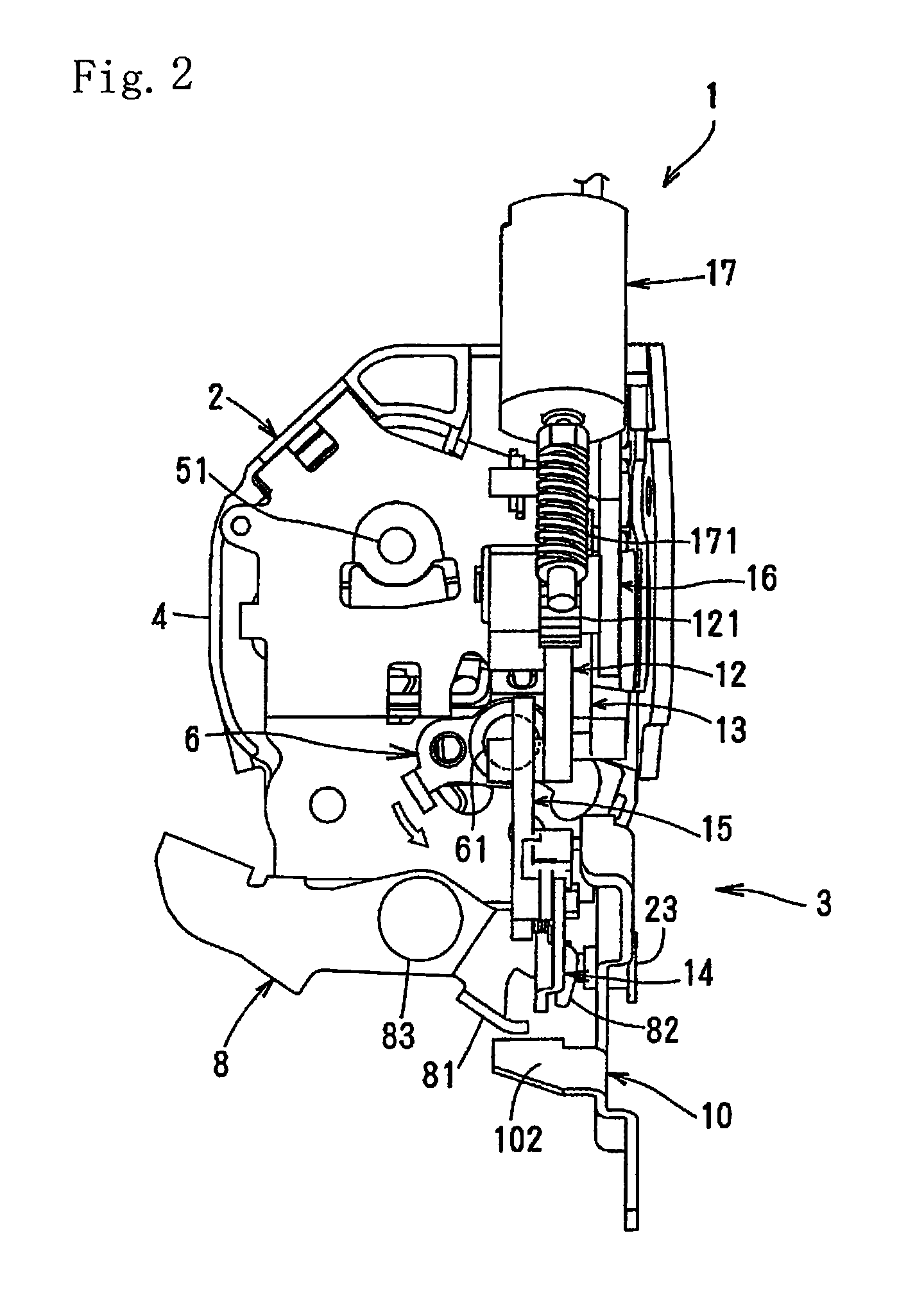
[0023]A door latch device 1 is disposed on the inside of a front door (hereinafter referred to “door”) at the rear end and comprises an engagement section 2 for holding the door in a closed position and an operating section 3 for operating the engagement section 2.

[0024]The door latch device 1 is provided on the inside of the door, is used in a door having no manually locking knob and is in an unlocking state, a locked state and a double-locking state. In the unlocking state, the door can be opened with either an outer handle (not shown) on the outside of the door or an inner handle (not shown) on the inside of the door. In the locked state, the door cannot be opened with the outer handle, but can be opened with the inner handle by double actions for changing the locked state to the unlocking state first and opening the door second. In the double locking state, the door cannot be opened by the outer or inner handle even if the double action of the inner handle is invalidated.

[0025]T...


PUM


Abstract

An operation mechanism section has a key lever that follows operation of a key cylinder, a lock lever that can move to an unlock position where operation of an operation handle is enabled and to a lock position where it is disabled, linkage levers that, when the lock lever is at the unlock or lock position, follows operation of the operation handle to make a door openable or not openable, and a motor that can move the lock lever to the unlock or lock position. The lock lever is formed by integrating together a gear section, a key operation input section, and an operation transmission section. The gear section is supported so as to be pivotable about a pivot shaft to the unlock and lock positions and directly meshing with a worm gear installed on the rotating shaft of the motor. The key operation input section is directly connected to the key lever. The operation transmission section is directly connected to the linkage lever.

Description

CROSS REFERENCE TO RELATED APPLICATIONS[0001]The present application is a 35 U.S.C.§371 National Phase conversion of PCT / JP2008 / 060598, filed Jun. 10, 2008, which claims benefit of Japanese Application No. 2007-242812, filed Sep. 19, 2007, the disclosure of which is incorporated herein by reference. The PCT International Application was published in the Japanese language.TECHNICAL FIELD[0002]The present invention relates to a door latch device for a motor vehicle comprising an engagement section and an operating section for operating the engagement section.BACKGROUND OF THE INVENTION[0003]A door latch device for a motor vehicle comprises an engagement section which engages with a striker on the car body and an operating section for controlling the engagement section. The operating section comprises a locking lever driven by a motor with a remote control switch and a key cylinder outside a door; an interconnecting lever connected to the locking lever and driven by a handle on the doo...

Claims


Application Information

Patent Timeline
Patent Type & Authority Patents(United States)
IPC IPC(8): E05B49/00B60J5/00E05B81/32E05B83/36
CPCE05B77/283E05B81/06E05B77/28E05B81/16E05B81/36E05B81/90Y10S292/23Y10T292/1047Y10T70/5155Y10T70/7102Y10T70/7107Y10T292/1082Y10T70/5889E05B77/30
Inventor FUJIHARA, YOSHIHIKO
Owner MITSUI KINZOKU ACT
Learn More