
Reconfigurable interface operable with multiple types of sensors and actuators

Active Publication Date: 2012-04-03
ACEINNA TRANSDUCER SYST CO LTD
View PDF60 Cites 58 Cited by
  • Summary
  • Abstract
  • Description
  • Claims
  • Application Information

AI Technical Summary

Benefits of technology

[0012]In one embodiment, the sensor information comprises initialization information representing a time required for initializing the sensor in the sensor assembly, and measure time information representing a time required for the sensor to return the sensor signal. The initialization information and the measure time information allow the module to manage power consumption associated with collecting the sensor signal from the sensor.

Problems solved by technology

Such conventional interface system produces less than optimal results when used in the modules of the WSN.
Conventional interface systems, however, do not provide mechanisms for reducing power consumption.
The increased power consumption due to such conventional interface systems shortens the operational time of the devices.

Method used


Image

  • Reconfigurable interface operable with multiple types of sensors and actuators
  • Reconfigurable interface operable with multiple types of sensors and actuators
  • Reconfigurable interface operable with multiple types of sensors and actuators

Examples


example interface

Structure

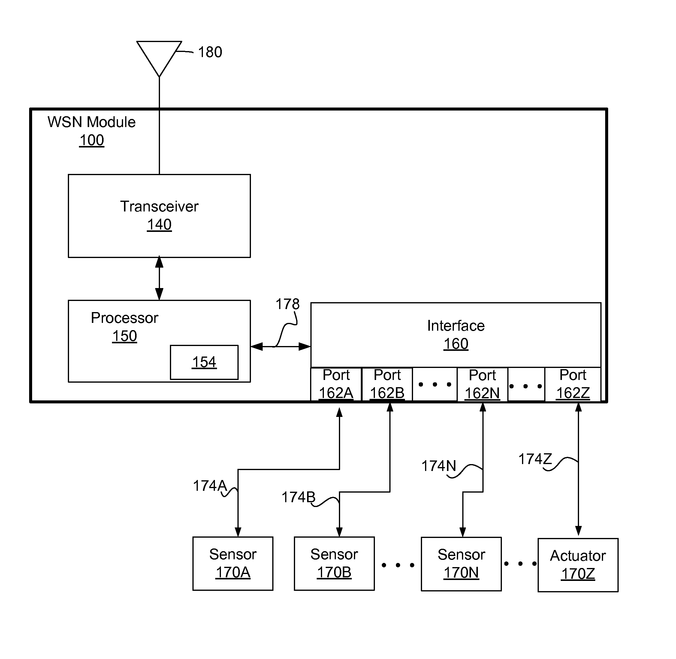
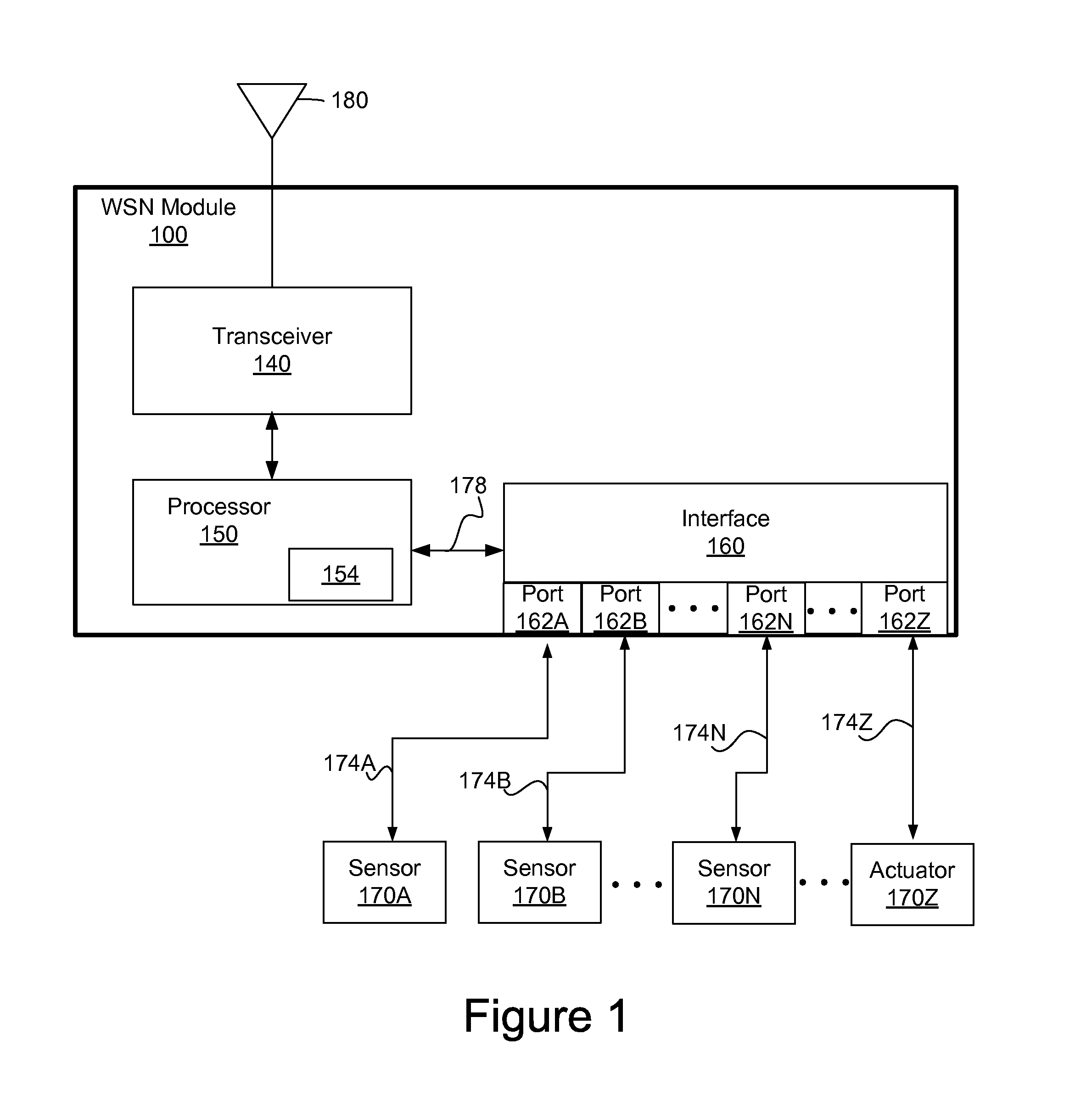
[0054]FIG. 4 is a circuit diagram illustrating the interface 160 of FIG. 1, according to one embodiment. The interface 160 may include, among other components, an A / D converter 410, a serial transceiver driver 408, a resistor R1, switches 426, 430, 434, 438, 442, 446, 450, 454, and a power source 402. The interface 160 receives control signals C2 through C10 from the processor 150 via the bus 178 to configure itself according to the sensor information.

[0055]The interface 160 may be coupled to sensors providing analog sensor signal, smart sensor providing digital sensor signal and actuators. The A / D converter 410 functions to receive analog sensor signal from the sensor and convert the analog sensor signal into digital data. The A / D converter 140 sends the converted analog sensor signal to the processor 150 via the bus 178. The serial transceiver driver 408 communicates with a smart sensor or a smart actuator via the port 162 to send commands to the smart sensor or the smart...


PUM


Abstract

An interface is provided that configures itself dynamically based on sensor information received from a sensor assembly or actuator information received from an actuator assembly. The interface may be configured to interoperate with sensor assemblies including analog transducers, smart transducers providing digital outputs and various actuators. The sensor information or the actuator information may include information for managing power consumption associated with the operation of the sensor or the actuator. Using the sensor information or the actuator information, a power management scheme may be implemented to reduce power consumption and extend the operational time of a module. The sensor information also includes information about the sensor signal generated by the sensor. The information about the sensor signal allows the module to interoperate with more diverse types of sensors.

Description

CROSS-REFERENCE TO RELATED APPLICATIONS[0001]This application claims priority under 35 U.S.C. §119(e) from co-pending U.S. Provisional Patent Application No. 61 / 039,859 entitled “Sensor Interface for Low-Power Nodes in a Wireless Sensor Network,” filed on Mar. 27, 2008, which is incorporated by reference herein in its entirety. This application is related to U.S. Pat. No. 8,005,108 entitled “Fast Deployment of Modules in Adaptive Network”; U.S. patent application Ser. No. 11 / 433,194 entitled “Adaptive Network and Method,” filed on May 11, 2006 which published as U.S. Publication 2007 / 0132846; U.S. Pat. No. 7,760,109 entitled “Interactive Surveillance-Network and Method”; U.S. patent application Ser. No. 11 / 152,350 entitled “Adaptive Surveillance Network and Method,” filed on Jun. 13, 2005 which published as U.S. Publication 2010 / 0013933; and U.S. Pat. No. 7,705,729 entitled “Surveillance System and Method,” all of which are incorporated by reference herein in their entirety.BACKGROU...

Claims


Application Information

Patent Timeline
IPC IPC(8): G08B29/00
CPCH04W4/006Y02B60/50H04W4/38Y02D30/70
Inventor MILLER, MATTHEWBROAD, ALAN S.
Owner ACEINNA TRANSDUCER SYST CO LTD
Learn More