
On-road energy conversion and vibration absorber apparatus

a technology of energy conversion and vibration absorption device, which is applied in the direction of machines/engines, traffic signals, roads, etc., can solve the problems of geographical restrictions and plant security threats, and achieve the effect of reducing the vibration of vehicles, absorbing and alleviating the vibration of vehicles

Inactive Publication Date: 2012-04-03
CHANG HUNG WEI +1
View PDF1 Cites 11 Cited by
  • Summary
  • Abstract
  • Description
  • Claims
  • Application Information

AI Technical Summary

Benefits of technology

[0010]It is another object of the present invention to provide an on-load energy conversion and vibration absorber apparatus that in addition to performing the energy conversion, the vibration of vehicles can also be absorbed and alleviated.
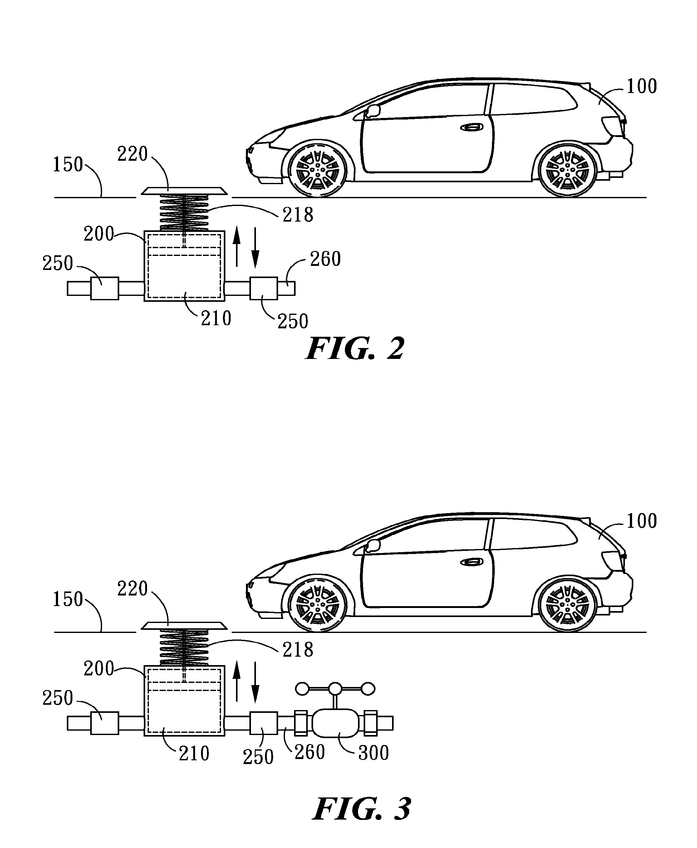
[0011]To achieve the above objects, the aforesaid apparatus comprises a restorable elastic compression unit to be laid on the road surface with a pressure receiver plate attached to the top thereof, and a pressure chamber is formed inside. The pressure receiver plate is for receiving the weights of those moving vehicles including motorcycles and bicycles and pedestrians weighing down thereon so as to compress and pressurize a fluid, mainly air, contained in the pressure chamber. An elastic compression unit is provided to support the pressure receiver plate and restore it to its initial position after the exerting weight is released. A fluid conduit with a check valve is installed abut on, and in connection with the pressure chamber, the check valve conducts the pressurized fluid to flow along the conduit in one direction and drives a vane wheel with a jet flow of the pressurized fluid by releasing it potential energy. The vane wheel in turn drives a generator to generate electric energy. And the vibration of the vehicles is alleviated by the cushion effect of the restorable elastic element.

Problems solved by technology

As it is well-known, the traditional steam power plant produces a large amount of carbon dioxide which aggravates the green house effect, the hydraulic power plant is destructive to natural environment in construction and power supply is not reliable during low water periods, and the nuclear power plant is said to be the most threatful to the security.
However, the both are sometimes geographically restrictive by reason of local climate.

Method used


Image

  • On-road energy conversion and vibration absorber apparatus
  • On-road energy conversion and vibration absorber apparatus
  • On-road energy conversion and vibration absorber apparatus

Examples


Embodiment Construction

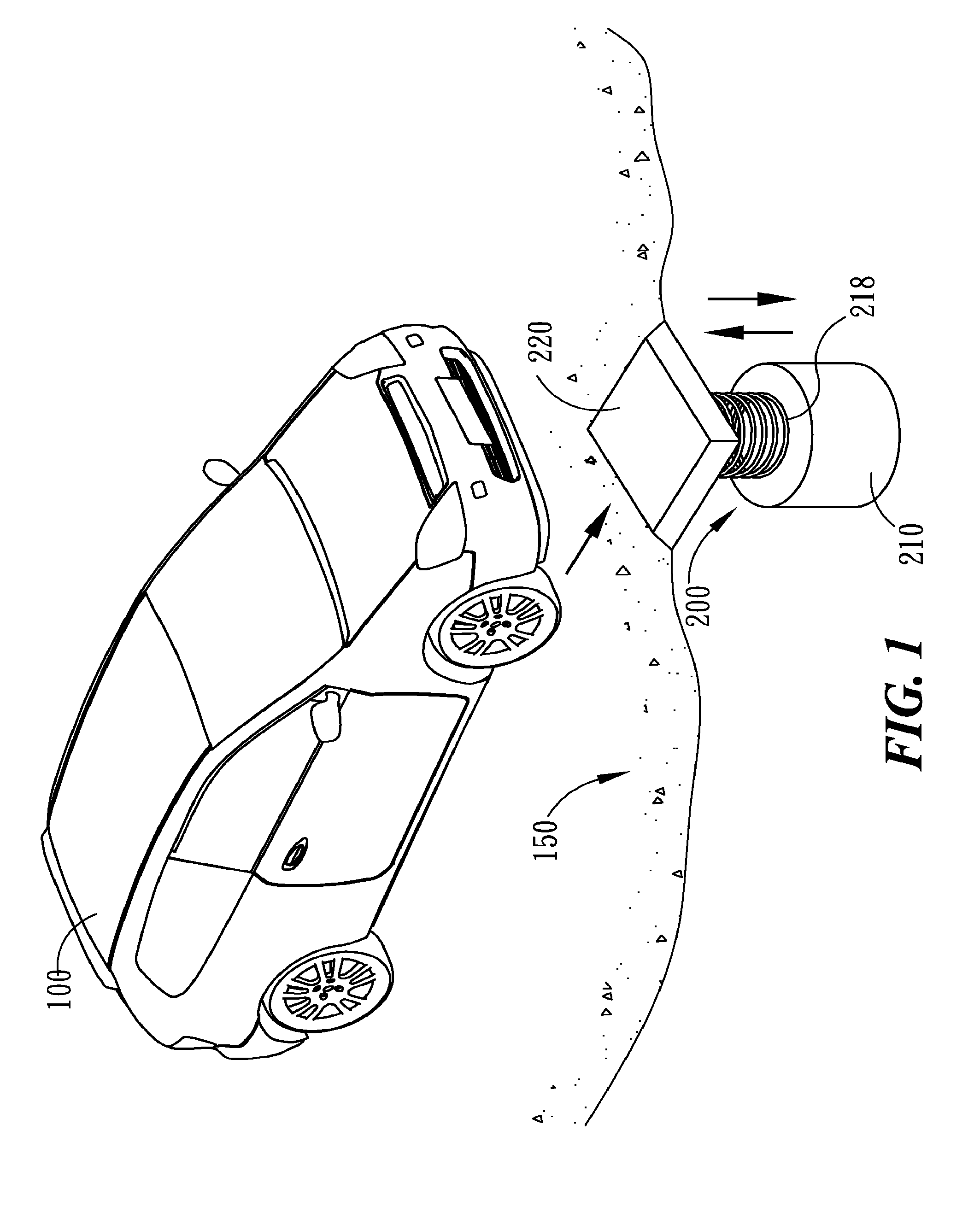
[0032]Referring to FIG. 1, the on-road energy conversion and vibration absorber apparatus receives the energy (static, kinetic energy of the rolling wheel) delivered by a vehicle 100 and even pedestrians when being weighed down on a pressure chamber 210 formed in a compression unit. The fluid contained in the pressure chamber 210 is pressurized to output a kinetic energy and at the same time, alleviating the vibration of the vehicle 100. In the apparatus, a compression unit 200 is installed beneath the road surface 150. When the vehicle 100 and pedestrians weigh down on a pressure receiver plate 220 of the compression unit 200, the fluid in the pressure chamber 210 is pressurized to store the potential energy and then conducted to pass through a check valve 250 to flow in one direction, and the vibration of the vehicle is also alleviated by the cushion effect of the restoring force of the compression unit 200 performed by a restorable elastic element 218. The restorable elastic elem...


PUM


Abstract

An on-road energy conversion and vibration absorber apparatus receives the kinetic energy from moving vehicles and pedestrians when being weighed down, and converts the received kinetic energy into a potential energy using a restorable elastic element compressing a fluid thereby storing the potential energy in a pressure chamber, and then conducting the pressurized fluid to pass though a check valve along a conduit and drive a vane wheel by releasing its potential energy. The vane wheel in turn drives a generator to generate electric energy, and the vibration of the vehicles is alleviated by cushion effect provided by the apparatus.

Description

CROSS-REFERENCE TO RELATED APPLICATIONS[0001]The present application is a continuation-in-part application of U.S. patent application Ser. No. 12 / 234,624 filed on Sep. 20, 2008 now abandoned, which is incorporated by reference herein in its entirety.BACKGROUND OF THE INVENTION[0002]1. Field of the Invention[0003]The present invention relates to an on-road energy conversion and vibration absorber apparatus in which the kinetic energy received from moving vehicles (including motorcycles and bicycles) and pedestrians are converted into a potential energy using a restorable elastic element to compress and pressurize a fluid, and then to drive a vane wheel by releasing the pressure of the pressurized fluid. The vane wheel in turn drives a generator to generate electric energy.[0004]2. Description of the Prior Art[0005]Continuous rising of the oil cost has been affecting the economy in the whole world that the problems of environmental protection, energy saving, carbon reduction and anti-...

Claims


Application Information

Patent Timeline
Patent Type & Authority Patents(United States)
IPC IPC(8): F02B63/04E01F9/529
CPCH02K57/00F03G7/08H02K99/00E01F9/529F03G7/083
Inventor CHANG, HUNG-WEILEE
Owner CHANG HUNG WEI
Learn More