
Air bearing surface method and apparatus optimizing flying height on demand efficiency during flying height on demand activity of slider in a hard disk drive

a technology of air bearing surface and flying height, which is applied in the direction of maintaining head carrier alignment, recording information storage, instruments, etc., can solve the problems of optimal mechanism possessed all of these limitations, and achieve the maximum of fod efficiency, high peak pressure area, and maximum fod efficiency

Inactive Publication Date: 2012-03-27
SAMSUNG ELECTRONICS CO LTD
View PDF3 Cites 1 Cited by
  • Summary
  • Abstract
  • Description
  • Claims
  • Application Information

AI Technical Summary

Benefits of technology

The patent describes a method and apparatus for controlling the air flow over the air bearing surface of a slider in a hard disk drive during a Flying height On Demand (FOD) operation. This is achieved by providing an FOD protrusion on the slider, which deforms the air bearing surface and changes the air bearing pressure map, resulting in a maximum FOD efficiency. The method includes providing an air bearing surface with the FOD protrusion, minimizing the peak pressure under the FOD operation, placing the peak pressure off the FOD area created by the FOD protrusion, and shrinking the high peak pressure area. The slider may also include a read head and a micro-actuator for creating the FOD protrusion. The head gimbal assembly and the head stack assembly are also discussed. The technical effects of this patent include maximizing the FOD efficiency and improving the performance of the hard disk drive.

Problems solved by technology

The optimal mechanism possesses all of these limitations.

Method used


Image

  • Air bearing surface method and apparatus optimizing flying height on demand efficiency during flying height on demand activity of slider in a hard disk drive
  • Air bearing surface method and apparatus optimizing flying height on demand efficiency during flying height on demand activity of slider in a hard disk drive
  • Air bearing surface method and apparatus optimizing flying height on demand efficiency during flying height on demand activity of slider in a hard disk drive

Examples


Embodiment Construction

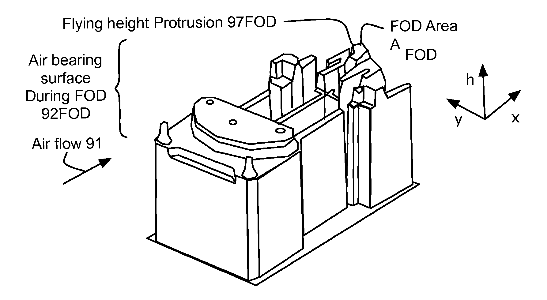
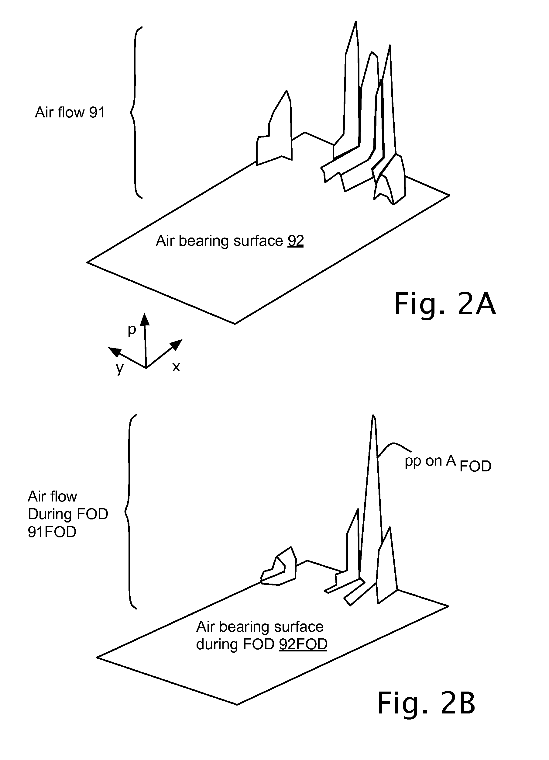
[0040]This application relates to an air bearing surface 92 of a slider 90 accessing a rotating disk surface 120 in a hard disk drive 10, in particular to controlling air flow 91 over the air bearing surface during a Flying height On Demand (FOD) operation using an FOD protrusion 97FOD on the air bearing surface.

[0041]The aspects of the invention include a method of controlling air flow 91 over the air bearing surface 92 of a slider 90 during a Flying height On Demand (FOD) operation of the slider over a rotating disk surface 120 in a hard disk drive 10 as shown in FIGS. 1A to 2B. As used herein the FOD operation includes the formation of an FOD protrusion 97FOD on the slider, which deforms the air bearing surface. This deformation of the air bearing surface changes the air bearing pressure map as shown in FIGS. 2A and 2B, and the slider flying height, or vertical position Vp over the rotating disk surface as shown in FIGS. 3A and 3B. The FOD efficiency EFOD was calculated as the ve...


PUM

PropertyMeasurementUnit
speedaaaaaaaaaa
speedaaaaaaaaaa
speedaaaaaaaaaa

Abstract

A slider including air bearing surface with Flying height On-Demand (FOD) protrusion with method of controlling airflow to maximize FOD efficiency as ratio of change in vertical position to protrusion height. Slider including components controlling the air flow to maximize FOD efficiency and / or including specific components minimizing an air bearing pressure under a Flying height On Demand (FOD) operation away from a maximum air bearing pressure, placing a peak pressure off of an FOD area create by a FOD protrusion, and shrinking a high peak pressure area of the air bearing surface. Hard disk drive includes head stack assembly, which includes head gimbal assembly, which includes the slider. Manufacturing method for slider, head gimbal assembly, head stack assembly and hard disk drive, and these items as products of these processes.

Description

TECHNICAL FIELD[0001]This application relates to an air bearing surface of a slider accessing a rotating disk surface in a hard disk drive, in particular to controlling air flow over the air bearing surface during a Flying height On Demand (FOD) operation using an FOD protrusion on the air bearing surface.BACKGROUND OF THE INVENTION[0002]The Flying height On Demand (FOD) protrusion deforms an air bearing surface, which changes air bearing pressure and the slider flying attitude. While this is generally known, knowing what to optimize is not. A performance metric is needed which can be used to optimize air bearing surfaces and FOD protrusion of these air bearing surfaces.SUMMARY OF THE INVENTION[0003]One aspect of this application is a method of controlling air flow over the air bearing surface of a slider during a Flying height On Demand (FOD) operation of the slider over a rotating disk surface in a hard disk drive. As used herein the FOD operation includes the formation of an FOD ...

Claims


Application Information

Patent Timeline
Patent Type & Authority Patents(United States)
IPC IPC(8): G11B21/02
CPCG11B5/3136G11B5/6005G11B5/6064G11B5/6082G11B5/607
Inventor ZHANG, SHUYU
Owner SAMSUNG ELECTRONICS CO LTD
Learn More